When you’re concentrating on the engine itself, it’s easy to forget that the object of the whole thing is to turn the propeller. Whilst it’s true that there is little that can go wrong with a propeller, apart from physical damage such as bent, chipped or broken blades, it’s worth being sure that you’ve got the right one for the job; a propeller needs to be carefully matched to the boat, engine and gearbox.
The science of propellers is remarkably complicated, but you can think of a propeller in any of three ways:
- as a screw
- as a pump, or
- as a foil.
None of them tells the whole story, but between them they provide a working knowledge of a subject which could easily fill several books, each much bigger than this one.
The propeller as a screw
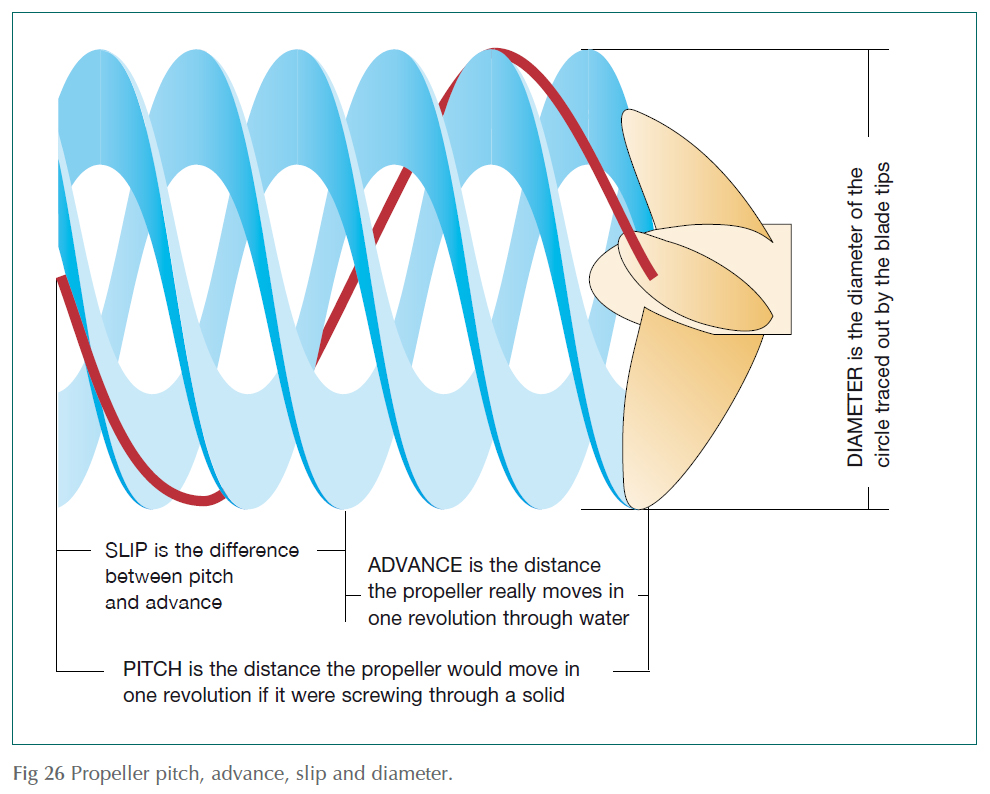
One theory regards the propeller as a screw, winding its way through the water like a bolt winding its way into a nut. It’s not a very good theory, because a propeller doesn’t work in a solid medium, but it explains some of the terminology.
Pitch is the distance the propeller would move in one revolution if it were screwing its way through a solid. In practice it does not move quite that far: the distance it really moves is called the advance. The difference between pitch and advance is called slip.
The picture is complicated by the fact that the advance isn’t quite the same as the distance the boat moves: for one thing the boat tends to drag some water along with it, and for another, the water directly affected by the propeller tends to move astern compared with the water nearby. This makes it very difficult to measure the true slip. It’s very much easier to find the apparent slip, which is the difference between the boat’s movement and the pitch. For highperformance motorboats, the apparent slip may be as little as 10 per cent of the pitch, but for a heavy motorsailer or workboat it can be as much as 50 per cent.
The propeller as a pump
Another theory treats the propeller as a pump, squirting water backwards. Newton’s third law of motion says that for every action there is an equal but opposite reaction, so if the propeller pushes a lump of water backwards, the water also pushes the propeller (together with the boat to which it is attached) forwards.
The amount of water the propeller can push in a given time depends mainly on the power available: a 100 hp engine, for instance, can move about 50 ft3 per second. You can think of that 50 ft3 of water as being in the shape of a cylinder, whose diameter is roughly the same as that of the propeller, and whose length is roughly the distance the prop has moved through the water in the time. For a slow motor cruiser, moving at 10 ft/sec, that means the cylinder must have a cross-section of 5 ft2, or a diameter of about 30 in. For a sportsboat doing 50 ft/sec with the same engine, the cylinder’s cross-section must be reduced to 1 ft2, or about 13 in.
This suggests – correctly – that the diameter of a propeller should vary depending on the power transmitted (because that determines the volume of water it can move in one second) and the speed at which the boat is moving (because that determines the length of the cylinder).
The propeller as a foil
A more recent, realistic and complicated theory regards each blade of the propeller as a foil, like a boat’s sail or an aircraft’s wing.
Like a sail, the blade has to be at a slight angle to the fluid flowing over it if it is to generate any useful force. Unfortunately, increasing this angle of attack doesn’t just increase the useful thrust: it also increases the drag – which is one of the reasons why over-sheeting a sail makes it less efficient.
For a sail, the optimum angle between the sail and the air flow is about 20–25°, but for a propeller blade in water it is much smaller – about 4°.
The analogy with sailing goes on if you think about how the flow across the propeller blade is created. The ‘apparent wind’ flowing across a sail is made up of two components: the ‘true wind’ that would be felt if the boat were stationary, and the ‘induced wind’ caused by its own movement through the air. In the case of a propeller blade, the equivalent of the true wind is created by the rotation of the propeller, while its ‘induced wind’ is caused by its movement through the water.
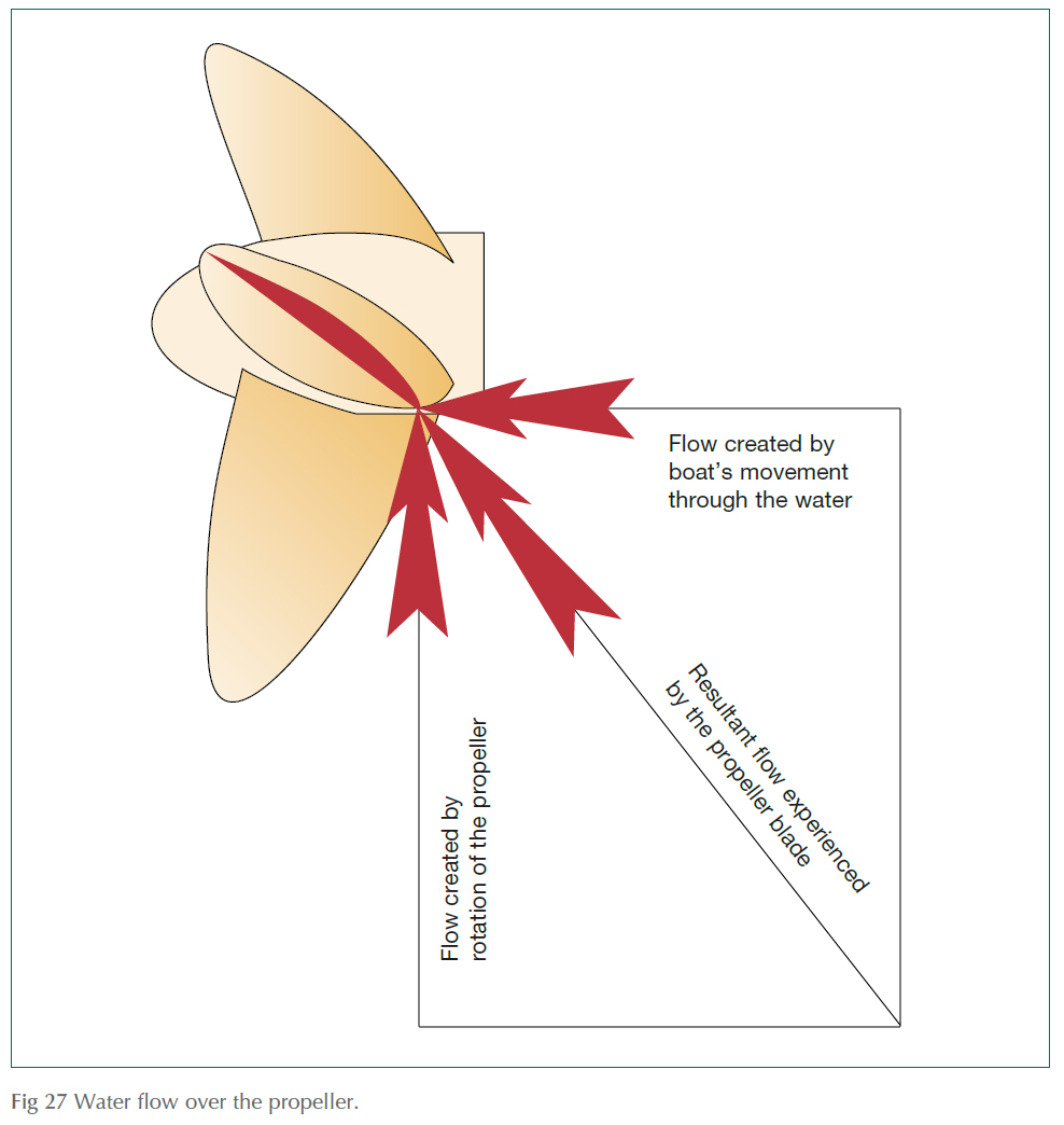
That is why a propeller blade needs to be twisted: ‘induced wind’ is much the same all over the propeller, but the ‘true wind’ varies dramatically, because the tip of each blade sweeps around a much bigger circle than the sections of the blade that are nearer the shaft.
It also suggests that the pitch of the propeller needs to be carefully matched to the speed at which the water is moving through the propeller: a fast boat generally needs much more pitch than a slow one, in order to cope with the much greater ‘induced wind’.
Choosing a propeller
What all this boils down to is that the choice of propeller depends on a mass of interrelated variables that include:
- the power available
- the shaft speed, and
- the speed of the propeller through the water.
There are so many variables (even the temperature and salinity of the water have a part to play) that trying to work out the pitch and diameter of the ideal propeller for a particular boat from pure theory is almost impossible: it is invariably better to leave it to a specialist such as a propeller manufacturer who will have access to a mass of experience and information, and can probably come up with the right answer simply by tapping a few vital statistics into a computer. It’s important to do so, because the wrong propeller can easily make a big difference to the boat’s performance.
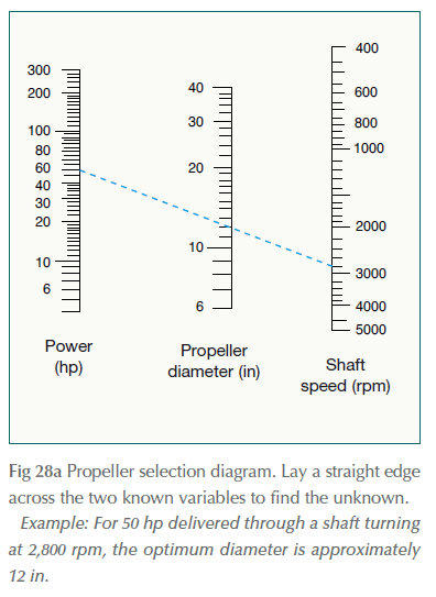
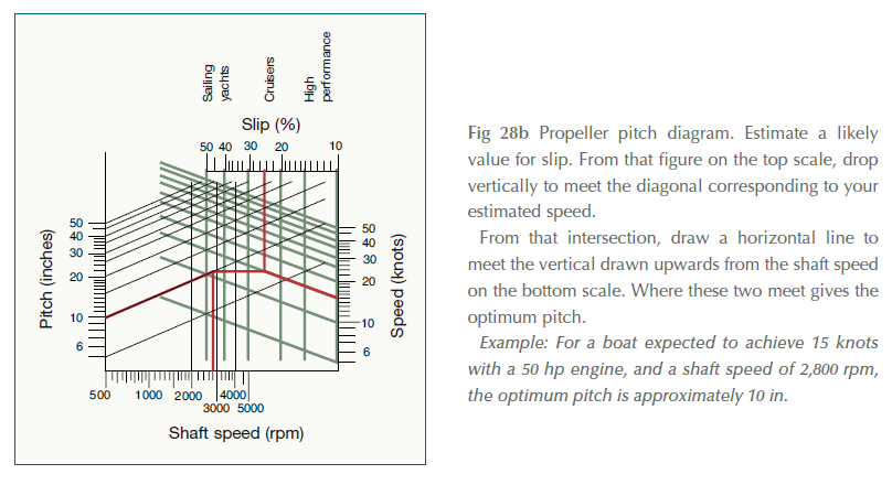
If you want to do a quick check, however, the diagrams (Fig 28a and 28b) provide a reasonably accurate estimate of the appropriate diameter and pitch.
Cavitation and ventilation
Although the words ‘cavitation’ and ‘ventilation’ are often used interchangeably, they are really two quite different things. What they have in common is that they can rob a propeller of almost all its grip on the water.
Ventilation is most common on sports boats and on sailing boats with outboard motors mounted high on their transoms, because it is caused by air being sucked into the propeller. A propeller designed to operate in water obviously can’t work very well in air: it generates very little thrust and suffers very little drag, so the engine speed increases while the boat slows down.
Cavitation is caused by the propeller itself. As it rotates, it creates thrust by increasing the pressure on the aft faces of its blades and simultaneously reducing the pressure on their forward faces. As the pressure falls, the boiling point of water reduces, eventually reaching the stage at which it will boil, even at sea temperature. When this happens, bubbles of water vapour form on the forward face of the propeller. The immediate effect of severe cavitation is very much like ventilation: the engine races but the propeller ceases to generate much thrust. The long-term effect of even minor cavitation is an erosion of the propeller blades known as ‘cavitation burn’, caused by the collapsing bubbles.
Cavitation can be caused by using the wrong propeller for the boat, such as one with too much pitch or not enough blade area, but can also be caused by damage to the propeller, such as nicks in the leading edge of the blade.
Stern glands
It may be stating the obvious to say that a propeller works best in water, and that an engine (generally) works in the air inside the boat, but it’s an important point because it means that somehow the shaft that turns the propeller has to pass out through a hole in the hull without letting water in. The component responsible is a stern gland.
Engineers have faced this problem for centuries, and one can imagine the joy of some Egyptian farmer when he discovered that his slave-powered irrigation pump worked better if he stuffed reeds around the handle to stop it leaking, or the relief felt by a Viking longship’s crew when they found they got less wet if they used rags to fill the gaps between their oars and the row of shields.
Those simple discoveries were the direct ancestors of what is still the commonest kind of stern gland – the ‘stuffing box’.
Stuffing boxes
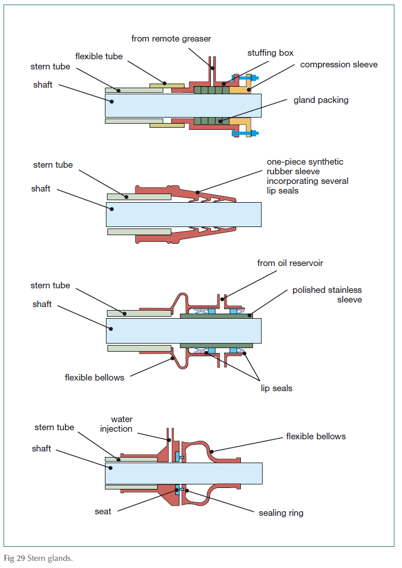
A stuffing box is basically an extension of the boat’s stern tube – the tube that carries the propeller shaft out through the hull – enlarged to form an outer casing that is filled with rings of greasesoaked packing. A sleeve around the shaft holds the packing in place, and can be tightened down to compress the packing so that it forms an almost watertight seal. A common refinement – essential for engines mounted on modern ‘soft mounts’ – is a short length of flexible tube between the stern tube and the stuffing box, to allow the stuffing box to move with the shaft as it vibrates.
Another is a reservoir of grease, so that the packing can be re-greased without having to dismantle the whole thing. Obviously this only works if you use it, so it makes sense to get into the habit of tightening the greaser every time the engine is used.
Even with a good supply of fresh grease, an inevitable problem with a traditional stuffing box is that if the stuffing is compressed tightly enough to make a perfect seal, there would be so much friction that the packing would get hot – drying out the grease and wearing away both the packing and the shaft. For this reason, a stuffing box should never be tightened down so much that it is completely dry: a slight leak helps cool and lubricate it without imposing too much strain on the bilge pump. This is so important that on planing boats, where the movement of the boat itself might suck water away from the stern gland, water is often pumped into the stuffing box by the cooling system.
Other shaft seals
This perceived ‘problem’ of essential leakage – and the rather fiddly job of re-packing – has led to the development of several more modern alternatives.
Some use a synthetic rubber diaphragm clamped to the shaft or stern tube to hold a ceramic or carbon sealing ring in firm contact against a phosphor bronze or stainless-steel seat. The virtue of this is that there’s nothing rubbing against the shaft, and no need to mess about with grease: the only maintenance required is occasionally to pull the diaphragm away from the seat, to flush out any debris and stop the two parts sticking together if the boat is left idle for any length of time.
Another consists of a hollow rubber cone with a row of lip seals – similar to those that prevent oil escaping from the engine itself – moulded into its inner surface. These need greasing once a season or every 200 hours, and have to be ‘vented’ to ensure that they are full of water each time the boat is launched.
A third variety keeps water out by surrounding the shaft by a tube filled with oil. Lip seals keep the oil inside the tube, by sealing against a polished stainless-steel sleeve fitted to the shaft.
Outdrives and saildrives
Outdrives and saildrives circumvent the need for a stern gland altogether by – in effect – extending the gearbox right into the water in the form of a drive leg. Of course, this doesn’t make the problem go away altogether: it just changes it a bit, because instead of having to seal the gap around a small rotating shaft, there’s a much bigger hole to plug between the hull and the drive leg. Outdrives achieve this by using flexible rubber bellows between the transom and the leg, while saildrives use a rubber diaphragm to seal the joint between the drive unit and the bottom of the boat. Servicing recommendations vary depending on the manufacturer and model, but the importance of following them to the letter is obvious.
... Things to do
PROPELLERS
It is a good idea to remove the propeller from time to time, to stop it seizing solid on the shaft. This is particularly important in the case of outboard and outdrive propellers, which usually have either shear pins or flexible hubs that are designed to protect the engine and transmission by slipping or breaking if the propeller hits something. Unfortunately, after a period of time, these protective devices break of their own accord, so it’s important to make sure that the propeller can be taken off and replaced at sea.
REMOVING A PROPELLER
- a. Straighten out the legs of the split pin and remove it, or flatten the lugs of the tab washer that holds the propeller nut in place.
- b. Use a block of wood to stop the propeller turning, and undo the propeller nut.
- c. It should be possible to pull an outboard or sterndrive’s propeller off the shaft by hand. Make a note of the order that any springs or washers come off, and which way round they go.
- d. The best way to remove a stubborn propeller is with a puller. Once the puller has been tightened, a few light taps with a hammer on the puller should make the propeller slide off.
- e. As a last resort, try warming the propeller boss with a blow lamp.
REPAIRING A PROPELLER
If necessary, use a file to smooth any burrs or nicks from the edges of the propeller, but be careful not to remove so much metal that there is a risk of the propeller becoming unbalanced. If it is badly damaged, refer it to a propeller repair workshop.
Replacing a propeller
- a. Before replacing the propeller, grease the shaft with a non-graphite grease.
- b. Slide the propeller back on, making sure that any keys, shear pins, springs or washers are replaced exactly as they were removed, but use a new tab washer (if there was one) to hold the propeller nut in place.
- c. Tighten the propeller nut just sufficiently to grip the propeller, then insert the split pin (if there was one). Bend up one tab of the tab washer to hold the nut in place, or open the legs of the split pin and bend them round the nut.
STERN GLANDS
1 GREASING A STERN GLAND
If your stern gland is fitted with a greaser, routine greasing involves either turning the handle or tightening the cap by one turn after every few hours’ running: once every four hours is about right. Eventually, this will use up all the grease, which will have to be replaced. Don’t use graphite grease: its carbon content causes extremely rapid corrosion in the presence of salt water.
- a. Remove the top cap of the greaser. If yours is the type that uses a handle like that of a garden tap to operate a plunger, ‘unscrew’ the handle to return the plunger to its starting position.
- b. Invert the grease can, so that the hole in the plastic disc is over the greaser.
- c. Press the whole can downwards, so that the plastic disc slides into the can and forces grease out. You may have to stop a few times, especially when the greaser is nearly full, to allow trapped air to escape.
- d. Replace the cap of the greaser.
2 ADJUSTING A STERN GLAND
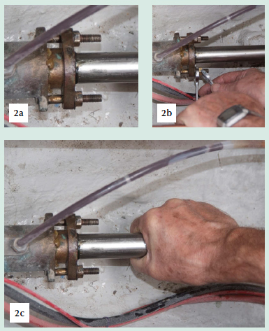
- a. With the engine stopped and out of gear, turn the shaft by hand to get a feel for how stiff it is.
- b. Slacken off any lock-nuts holding the two parts of the stern gland together. Tighten the clamping bolts that hold the two parts of the stern gland together, or screw the sleeve into the outer casing. Don’t tighten them by more than half a turn at a time, and – if yours is the type that has two or three bolts – make sure that you tighten them evenly.
- c. Turn the shaft by hand and check for drips: it should turn freely and leak between one and six drips per minute. If it is leaking too quickly, tighten the clamping bolts further.
3 RE - PACKING A STERN GLAND
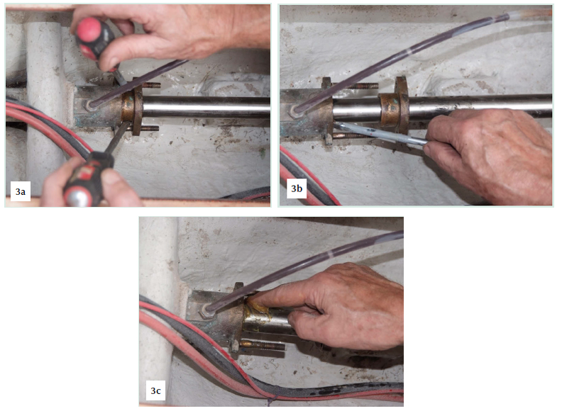
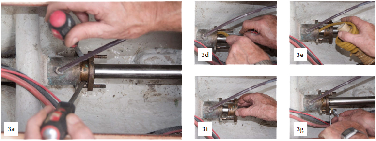
If the stern gland cannot be tightened enough to reduce the leakage to an acceptable level without making the shaft unduly stiff to turn, then the packing needs to be replaced. This can only be done with the boat out of the water. (Photos 3a–g show the stern gland viewed from above.)
- a. Remove the lock-nuts and nuts that hold the two parts together, or unscrew the two parts completely. If necessary, use two large screwdrivers or pinchbars to prise the two parts apart.
- b. Remove the old packing. This will probably involve fashioning some home-made ‘tools’, such as a small screwdriver filed to a point, or bent coat-hanger wire.
- c. Use a degreasing agent (such as ‘Jizer’ or ‘Gunk’) to clean the shaft and stern gland.
- d. Check that the new packing is the right size: it should just fit the gap between the shaft and the outer casing of the stern gland.
- e. Wrap the packing around the shaft, making sure that it sits squarely on the shaft, and then use a sharp craft knife to cut through the packing along the line of the shaft so as to produce several short lengths of packing, each just long enough to fit round the shaft. Use the stern gland’s end cover to push each ring of packing down into the stern gland case, making sure that each one sits squarely on the shaft and that its cut ends are not lined up with the cut ends of the one before.
- f. Reassemble the end cover and clamping bolts, but leave them finger-tight. Turn the shaft several times by hand in order to help bed the packing rings together.
- g. As soon as the boat is re-launched, adjust the stern gland to the required slow drip.
References
Adlard Coles Book of Diesel Engines

