Why choose a diesel?
Compared with a petrol engine, for instance, a diesel engine is likely to be expensive, heavy and slow to respond. On most boats, though, these drawbacks are worth putting up with in order to take advantage of a diesel’s main attributes:
- Reliability
- Long life expectancy
- Low running costs
- Non-explosive fuel
Even a diesel engine, however, will deteriorate if it is neglected, and could ultimately corrode away to become a useless lump of rusty metal. To take advantage of its reliability and long life expectancy it needs to be looked after. Of course you can pay someone else to do the work for you, but that eats away at the advantage of low running costs.
The aim of this book is to help you get the most out of the capital invested in your engine, by making the most of the advantages you’ve already paid for – reliability, longevity and economy.
A fringe benefi t of doing your own maintenance will be familiarity with your engine and the tools you use to work on it. Then, if things do go wrong, you have a sporting chance of either being able to solve the problem yourself, or of giving a professional mechanic something more to go on than ‘it just sort of stopped’.
The most fundamental of all those processes takes place deep inside the engine. It’s the one that gives internal combustion engines their name, because it involves burning air and fuel inside a confi ned space.
THE BASIC PROCESS
The confi ned space is the cylinder – a vertical tube, machined into the heavy metal block that accounts for most of the engine’s weight and bulk. The top of the cylinder is closed by another heavy casting called the cylinder head. Tunnels in the cylinder head allow air and exhaust gas to fl ow in or out of the cylinder, controlled by valves.
The bottom of the cylinder is formed by the piston, another machined metal casting that is designed to slide up and down inside the cylinder, with springy metal piston rings forming an almost gas-tight seal between the piston and the cylinder walls.
Don’t bother, for the moment, about how we get a mixture of fuel and air to burn inside the cylinder: just accept that as it burns it produces a mixture of water vapour, carbon dioxide and small quantities of some more unpleasant gases, such as sulphur dioxide and oxides of nitrogen. It also gets very hot.
The rise in temperature makes this gaseous cocktail expand – increasing the pressure within the cylinder, and driving the piston downwards. The piston is attached to a connecting rod, or ‘con rod’, whose other end is coupled to the crankshaft. Just as the cranks of a bicycle convert vertical movements of the rider’s legs to a rotary movement of the wheels, the crankshaft converts the downward thrust of the piston into a rotary movement of the shaft.
One end of the crankshaft carries a heavy metal flywheel. Once the fl ywheel has started turning, its momentum keeps it going, so the crankshaft keeps turning with it – pushing the piston back up the cylinder. As it does so, one of the valves in the cylinder head opens, allowing the hot gases to escape.
As soon as the piston reaches the top of its travel, the still-spinning fl ywheel and crankshaft drag it back down again. At this point, the exhaust valve shuts and the inlet valve opens, allowing fresh air to fl ood into the expanding space inside the cylinder.
This time, as the piston reaches the bottom of its stroke, the inlet valve closes. With both valves shut, and the momentum of the fl ywheel driving the piston back up again, the air inside the cylinder is compressed.
If you compress any gas, it gets hot. You can feel the effect for yourself by putting your fi nger over the outlet hole of a bicycle pump and pumping the handle. Even after several hard strokes, a bicycle pump is unlikely to develop more than about 100 psi, but the pressure inside a diesel engine’s cylinder rises to over 500 psi in less than 1/100 second. Its temperature rises, as a result, to something in the order of 800° C.
Diesel fuel doesn’t burn easily under normal conditions, but if you spray a fine mist of it into hot pressurised air, it will ignite spontaneously. The engine’s fuel system is designed to do exactly that – producing, in the cylinder, the burning mixture of air and fuel required to start the cycle all over again.
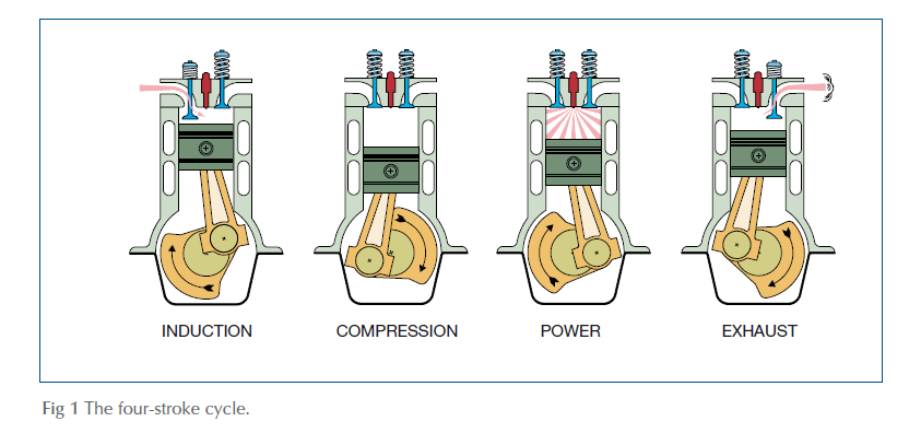
So there you have it: the basic operating cycle of a diesel engine, made up of four distinct strokes of the piston. You can think of them, if you like, as ‘suck, squeeze, bang, blow’, though in more conventional terminology they’re called Induction, Compression, Power and Exhaust.
VALVES
The work of the valves is vital to the whole sequence: they have to open and close at precisely the right moments, allowing an unrestricted flow of air or exhaust gas when they’re open, yet forming a perfectly gas-tight seal when they’re shut.
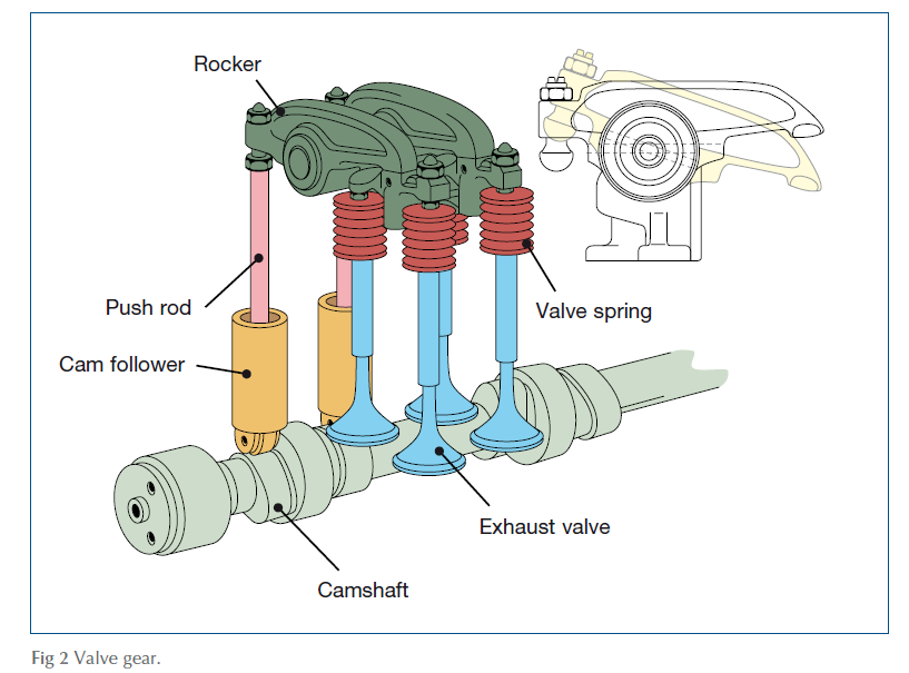
Each valve is roughly mushroom-shaped, with a long straight stem and a flat circular head, whose edge is bevelled and precision-ground to match the slope of the hardened valve seat that surrounds the mouth of the tunnel in the cylinder head. For most of each cycle, each valve remains shut, pulled firmly against its seat by one or two very strong valve springs. It’s opened, when necessary, by a component called a rocker, like a miniature seesaw that pivots on another shaft running across the cylinder head.
Meanwhile, a component called the camshaft is being driven by the crankshaft, but at half the crankshaft’s speed. On it are carefully machined bulges, called cams, that are shaped and positioned so that each in turn pushes upwards against a rocker at the right moment in each cycle. As one end of a rocker is pushed upwards, the other end moves downwards to push the valve open.
Although the principle is standard, there are plenty of variations on the theme. The camshaft, for instance, may be driven by gears, or by a chain and sprocket system, or by a toothed rubber belt, and it may be mounted high on the engine with the cams pushing directly on the rockers; or lower down and relying on push rods to transmit the movement of the cams to the rockers. In this case, the ends of the push rods don’t rest directly on the cams but sit in small bucket-shaped components called tappets or cam followers. In some engines, the cam followers are fitted with rollers to reduce wear. In others, they are designed to rotate so as to spread the wear more evenly, while some engines have hydraulic tappets which adjust themselves to correct for wear as it happens.
Whichever of these applies to your particular engine, do bear in mind that the whole system will have been set up so that each valve opens and closes at precisely the right moment in the cycle. Small amounts of wear and tear can be corrected by means of a simple adjustment, but it’s asking for trouble to tinker with the gears, belt or chain unless you know exactly what you’re doing.
THE TWO-STROKE CYCLE
It seems rather wasteful to have the piston going up and down like a yo-yo, but only producing power on one of its four strokes. There is an alternative, called the two-stroke cycle. Apart from the fact that it produces power on every second stroke of the piston, the diesel two-stroke has very little in common with its petrol-oil counterparts on lawnmowers and outboards, and its use is mainly confined to the very large engines that drive ships. The one exception is the Detroit Diesel range, which includes two-strokes down to 270 hp.
They are physically different from conventional four-stroke diesels in that they have no inlet valves. Instead, air is pumped into the cylinder by a mechanical blower – a supercharger – through ports halfway up the cylinder walls. (See Fig 3.)
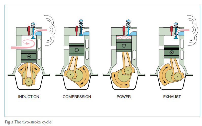
When the piston is at the bottom of its travel, these ports are above the level of the piston, so, with the exhaust valve open, clean air flows into the cylinder and blows the previous stroke’s exhaust gas out of the top.
As the piston rises, the exhaust valve shuts, and the piston itself closes the inlet ports, trapping the air inside the cylinder. The compression stroke continues, just as in a four-stroke engine, and is followed by the power stroke driving the piston downwards.
Just before the piston reaches the level of the inlet ports, however, the exhaust valve opens, allowing the exhaust gas to start escaping. As the piston descends still further, it uncovers the inlet port, allowing fresh air into the cylinder, to start the sequence all over again.
The advantages and disadvantages of two- and four-stroke engines are pretty evenly balanced: power for power, two-strokes are smaller and lighter, but are slightly less fuel-efficient, and because they are produced in very much smaller numbers they tend to be relatively expensive. Most of their repair and maintenance procedures are similar, though, so we’ll concentrate on the more common four-stroke engine throughout this book.
VARIATIONS ON A THEME
One apparently subtle variation is the distinction between direct and indirect injection.
Fig 1 illustrating the four-stroke cycle shows a direct injection engine: the fuel is sprayed directly into the cylinder. In practice, the top of the piston is usually carved away to form a hollow, called the combustion chamber, shaped to ensure that the fuel and air mix as thoroughly as possible.
In an indirect injection engine, the piston crown is usually flat, and the combustion chamber is deeply recessed into the cylinder head, with only a narrow opening between it and the cylinder. The idea is that the turbulence created when air from the cylinder is forced into the combustion chamber ensures more thorough mixing of the air and fuel, and a more progressive increase in cylinder pressure during the power stroke.
Historically, at least, indirect injection engines have been regarded as quieter and cleaner but harder to start, because the cylinder head absorbs a lot of the heat created during compression. Unfortunately, the heat lost to the cylinder head and the effort required to force air and burning gas in and out of the combustion chamber make them rather less fuel-efficient overall.
Developments in piston design are now allowing modern direct injection engines to catch up with the indirect engine’s advantages without the drawbacks, so indirect injection seems destined to fade away.

... THINGS TO DO
CHECKING VALVE/ROCKER CLEARANCES – ONCE PER SEASON
There isn’t much an amateur mechanic with a limited tool kit can (or should) do to the major components inside the engine apart from making sure that it has a good supply of fuel and air, and clean lubricating oil.
You can, however, check and adjust the gap between the rocker and the valve. There has to be a gap – usually about the thickness of a fingernail – to allow for the different rates at which the various components expand and contract as they warm up. Without it, there’s a very real risk that the valves won’t shut completely: they may even come into catastrophic contact with the pistons. If the gap is too large, the valves may not open as far as they should, and the engine will certainly be noisier than it should be.
a. Read the engine manual to find out what the valve/rocker clearances should be, and whether they should be adjusted with the engine cold or at normal running temperature. Note that the clearances for inlet valves may be different to those for exhaust valves, because exhaust valves get hotter.
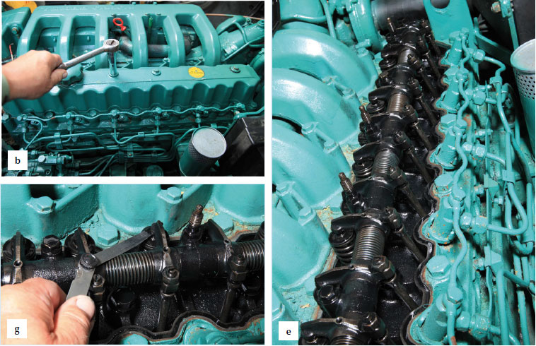
b. Remove the rocker cover – a relatively thin metal box on top of the engine, usually with the oil filler cap in the middle. Some engines have a separate rocker cover for each cylinder, or for each of two or three groups of cylinders.
c. Check the gap on each valve in turn, when the valve is completely closed and the gap is at its widest. There are two ways of finding out when this happens. On a multi-cylinder engine, the best way is to find the ‘magic number’ for your engine by adding one to the number of cylinders. For a four-cylinder engine, for instance, the magic number is five.
d. Turn the engine slowly by hand, if necessary using a spanner on the crankshaft (big nut on the lowest of the pulleys at the front of the engine). Watch the rockers moving as you do so, until the two rockers for one cylinder are ‘on the rock’ – that is, when one is rising and the other falling – signifying that this particular cylinder is at the end of its exhaust stroke and just beginning its induction stroke. Subtract the number of this cylinder from the ‘magic number’ to find the number of the cylinder that is ready to have its valve clearances checked. If, for instance, you have a fourcylinder engine and number 2 cylinder’s valves are on the rock, number 3 cylinder is ready, because 5 – 2 = 3.
e. On a single-cylinder engine, the clearance for one valve should be checked when the other valve is fully depressed. You can use this approach for a multi-cylinder engine, but it will take longer!
f. Slacken the lock-nut on the rocker whose clearance you are about to adjust, and then unscrew the threaded adjuster about one or two turns.
g. Set a feeler gauge to the clearance specified in the engine manual, and slip it between the valve stem and the rocker. Gently wiggle the feeler gauge while tightening the adjusting screw, until you can feel the feeler gauge being nipped between the valve stem and the rocker.
h. Leave the feeler gauge in place, and hold the adjusting screw with a screwdriver while you tighten the lock-nut. When it’s tight, wiggle the feeler gauge again to check that you haven’t upset the adjustment: you should feel a slight resistance, but it shouldn’t be jammed tight.
i. Repeat the process for each valve in turn, then replace the rocker cover, making sure that the cork or rubber sealing gasket is smooth, undamaged and properly seated.
References
Adlard Coles Book of Diesel Engines