One of the great virtues of a diesel engine is that it doesn’t need electricity to start or run. Small diesels can be started by hand, bigger ones by coiled springs, and the biggest of all by compressed air or separate starter engines.
An electric motor, though, is such a convenient way of doing the job that almost all marine diesels now have an electrical system of some description.
The basic system
Diesels intended for hand starting usually have decompression levers, which make it a lot easier to build up momentum in the heavy flywheel by opening the valves in the cylinder head to release the pressure in the cylinder.
Even so, hand starting a diesel can still be hard work, so it shouldn’t come as any surprise to fi nd that it takes a lot of electrical power to do the same thing – especially as electric-start engines don’t usually have decompression levers. Compared with any other electrical equipment on board, the amount of power involved is huge: the initial surge of current may be in the order of 1,000 amps. It quickly drops away to about 200 amps as the motor picks up speed, but it’s still asking a lot to expect any battery to start an engine more than once or twice without needing to be recharged.
This means that as well as the starter motor itself and a switch to control it, even the most basic electrical system is likely to include a dynamo or alternator to recharge the battery, and a regulator to stop the battery being overcharged. For indirect injection engines, there is usually also some kind of cold starting aid to make the starter motor’s job a little easier by warming the air in the cylinders.
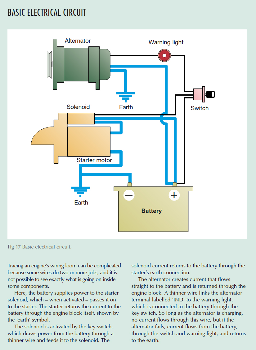
No ordinary switch can cope with the sort of currents involved in the starter circuit, so the ‘switch’ that controls the starter motor is actually a relay or solenoid – a remote-controlled switch operated by another switch on the control panel. The control panel also needs a warning light or buzzer to attract attention to any failure of the electrical system, so the complete system ends up looking something like that in Fig 17.
Making electricity
Generators and motors both depend on the close link between electricity and magnetism, which can be summed up by saying that if you move a wire in a magnetic field you’ll create electricity, and if you pass electricity through a wire you’ll create magnetism.
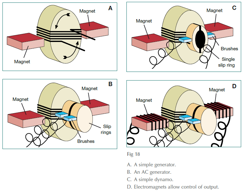
Fig 18A shows how this might be applied to make electricity: a coil of wire, wound around a central core, is spinning in the magnetic fi eld between two magnets. As it rotates, the wires that make up the coil move through the magnetic field, to generate an electric current.
Fig 18B shows one way of getting the electricity out of the coil: the ends of the wire are connected to brass slip rings, fixed to the spinning shaft. Selflubricating carbon brushes press against the slip rings to collect the electricity, and wires take it away to the rest of the system.
This is simple, but for practical purposes it has a major problem: because the coil is passing up through the magnetic field on one side, then down through it on the other, the current created in it is regularly changing direction.
Batteries can’t handle alternating current (AC): they need a one-way current (direct current, or DC). One possible solution is shown in Fig 18C. Instead of a pair of slip rings there is only one, split in half along its axis. Every time the current flow reverses, the connection to the outside world reverses as well, producing an intermittent but one-way current.
Dynamos
A real dynamo looks much more complicated than the contraption shown in Fig 18, but works in exactly the same way.
Instead of a single coil of wire, it has several, each wound around its own soft iron core. This, in turn, means that the two-piece ‘slip ring’ of the rudimentary dynamo has to be replaced by a commutator made up of several segments – one pair for each coil. This produces a smoother flow of current, because as the flow generated by one coil is reducing, the flow from another is increasing.
The other major refinement in a real dynamo is that instead of using permanent magnets to create the magnetic field, it uses electromagnets. They consist of soft iron cores bolted to the casing of the dynamo, and wrapped in coils of copper wire called the field windings. Passing an electric current through the field windings creates the magnetism.
The virtue of using electricity to make more electricity is that it allows the intensity of the magnetic field to be varied. A separate component called the regulator monitors the output of the dynamo and interrupts the power supplied to the field windings if the output rises too high, allowing the dynamo’s output to be controlled without having to adjust its speed.
Alternators
Dynamos are something of a rarity nowadays, having been almost completely replaced by a more efficient kind of generator called an alternator.
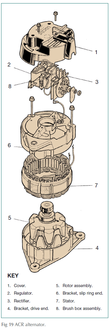
Mechanically, an alternator can be regarded as a dynamo turned inside out, with its field windings mounted on a spinning rotor in the middle, surrounded by a fixed ring called the stator, which carries the generating coils.
This arrangement leaves the coils stationary, but subjected to a spinning magnetic field. Having stationary generating coils means that an alternator can’t use a commutator arrangement to convert AC into DC: instead, it uses a solid-state electronic rectifier and regulator, usually built in under a plastic cover at one end of the alternator body.

As well as being more efficient than dynamos, alternators are generally more reliable and require little or no maintenance. Their main weakness is that their electronic components burn out very quickly if they are kept running with nowhere for the electricity to go, so it is essential to make sure never to disconnect an alternator while the engine is running – by switching the battery isolator switch off, for instance. If your installation allows you to stop the engine by turning a key, make sure it really has stopped completely before switching the key to the ‘off’ position.
Starter motors
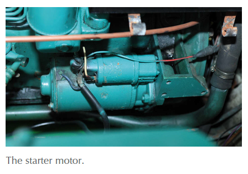
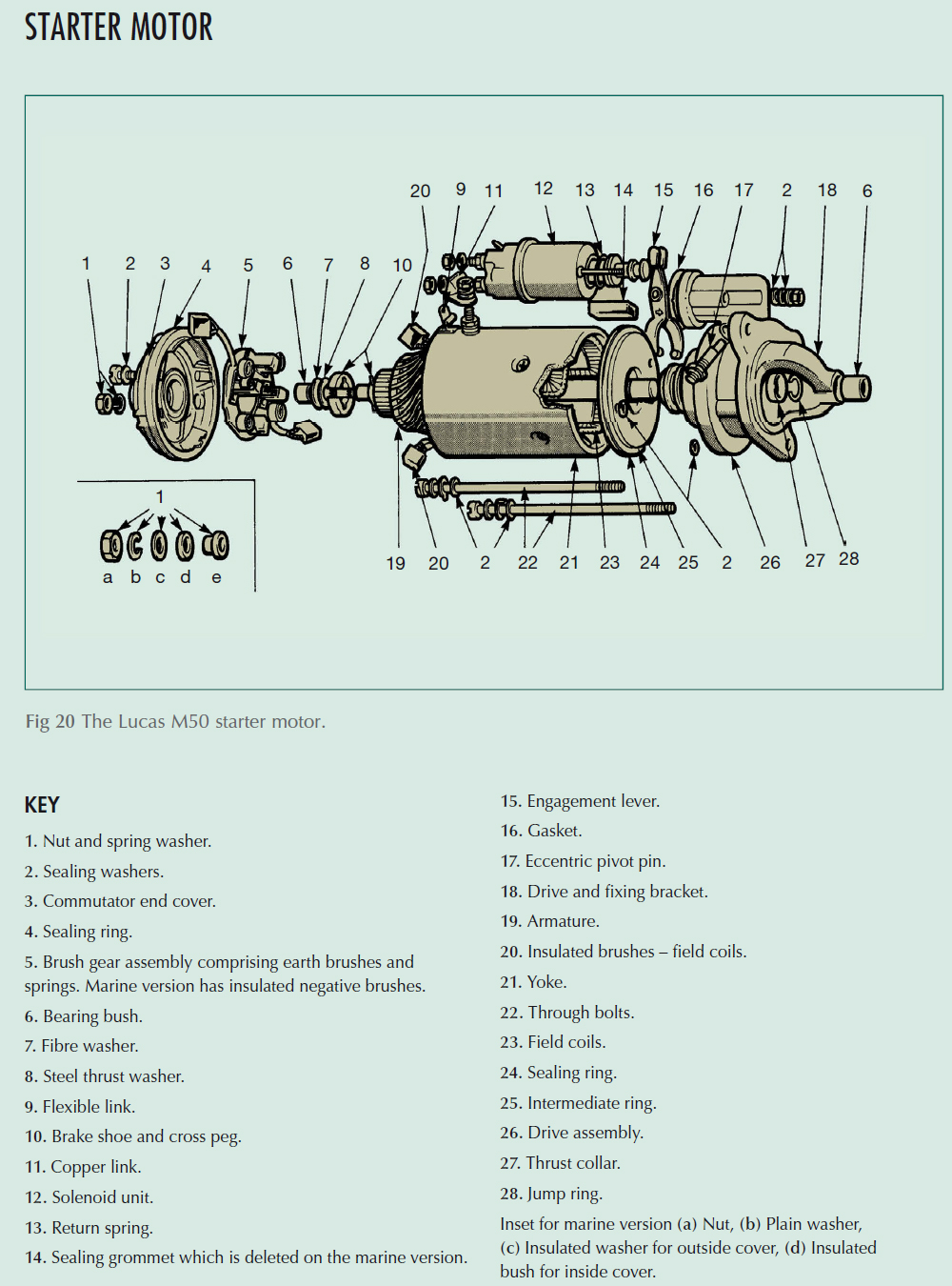
Structurally, an electric motor is very much like the rudimentary dynamo in Fig 18: it too has coils of wire mounted on a central shaft called the armature, and magnets bolted to the inside of the casing to create a magnetic field.
The big difference is that a motor uses electricity instead of creating it! When a current is passed through the armature coils, it creates a magnetic field that interacts with the magnetic field set up by the field windings in such a way that the armature is forced to rotate.
Dynastarts
A motor and a dynamo are so similar to each other that at one time there was a trend towards using a single component, called a Dynastart, to do both jobs. Unfortunately a good dynamo doesn’t make a good motor or vice versa, so this rather neat idea has now gone out of fashion.
Batteries
We can’t create energy: we can only convert it from one form into another. That is what happens inside the engine itself: chemical energy is released from the burning fuel and converted into mechanical energy. The alternator then converts some of that mechanical energy into electrical energy. Electrical energy, however, can’t be stored: to achieve that effect, the battery has to convert it back into chemical energy.
There are lots of ways of doing this, including the lightweight nickel-cadmium (NiCad) and nickel-metal hydride (NiMH) batteries used for mobile phones and hand-held radios. For the time being, however, these are too expensive to be used to store large amounts of power, so boats almost invariably use relatively cheap, low-tech lead-acid batteries.
The working part of a fully charged lead-acid battery is a stack of lead plates, interleaved with layers of lead peroxide and porous separators and surrounded by sulphuric acid. The acid tries to convert both sets of plates into lead sulphate while converting itself into water by rearranging the electrical charges that hold the molecules together. In the process, it creates an electric current between the positive peroxide plates and the negative lead plates.
Eventually, the sulphuric acid becomes so diluted that the reaction stops. The battery is then described as ‘flat’. The beauty of the leadacid battery, however, is that the whole process can be reversed by pumping electricity through it in the opposite direction. This converts the lead sulphate back into lead and lead peroxide, while the left-over sulphate turns the water back into sulphuric acid.
The system isn’t absolutely perfect, though. For one thing, the conversion process is never 100 per cent completed: repeated charging and discharging leaves some unconverted lead sulphate on the plates, gradually reducing the battery’s ability to ‘hold its charge’. Eventually, the accumulated lead sulphate flakes away, to lie useless in the bottom of the casing.
Another problem is that passing electricity through water – or through a solution of sulphuric acid in water – causes a process known as electrolysis, which breaks down the water into hydrogen and oxygen. For safety reasons, this potentially explosive mixture of gases should be vented overboard, but it’s important to appreciate that by doing so you’re effectively discharging water from the battery, which will have to be topped up with distilled or de-ionised water from time to time.
The demands of starting an engine are very different from those imposed by ‘ship’s services’ such as lighting and navigation equipment: the starter motor demands a lot of current for a few seconds at a time, while domestic and navigation equipment draws a relatively tiny current for hours at a stretch. Ideally, these contrasting requirements call for two different types of battery: a heavy duty battery for engine starting, and a deep cycle or traction battery for domestic loads. Structurally, the two types differ mainly in the number and thickness of their plates: a heavy duty battery has a large number of relatively thin plates, in order to expose as much surface area to the acid as possible, while a deep cycle battery has a smaller number of thicker plates in order to withstand the long-term effects of sulphation caused by being repeatedly discharged almost to the stage of being ‘flat’. ‘Marine’ batteries are a halfway house, intended mainly for small boats on which one battery may have to do both jobs.
Fuses and circuit breakers
Whenever an electric current passes through a wire it creates heat – and the heavier the current or the thinner the wire, the hotter it is likely to get. Taken to extremes, this could melt the insulation around the wire, or even start a fire. To stop this happening, designers should specify cables that are big enough to allow heat to radiate away from the wire naturally.
There is still an element of risk, though, because the current could – for all sorts of reasons – increase to levels far greater than the designer envisaged. To make sure this doesn’t happen, any properly installed electrical system incorporates some kind of excess current protection – either a fuse or a circuit breaker.
A fuse is a short piece of thin wire built into the system as a weak link that will heat up and break before the rest of the system suffers. The commonest type is similar to the fuse in a domestic plug, consisting of a short length of wire inside a glass tube. An increasingly common alternative is a small plastic peg with a strip of thin metal on the outside acting as the fuse. Both of these types have to be replaced as a complete unit when they ‘blow’. The much rarer alternative consists of a piece of replaceable wire mounted in a porcelain carrier, similar to that in an old-fashioned domestic fuse box.
Circuit breakers are taking over from fuses because although they’re more expensive, you don’t have to carry spares. Essentially, a circuit breaker is an automatic switch, which uses either the solenoid principle or the heating effect to switch itself off if the current flowing through it becomes dangerously high.
Fuses and circuit breakers occasionally ‘blow’ for no apparent reason. Although this is a nuisance, it’s essential not to give in to the temptation to replace a fuse with a bigger one, or to stop the breaker tripping with string or sticky tape! Find out why it’s blowing, and cure the cause, rather than disabling your protection just when it’s doing its job!
Solenoids
A solenoid is an electrically operated switch consisting of a coil of wire around a metal plunger. When electricity flows through the coil it becomes a magnet, and pulls the metal plunger into itself. This pulling action has all sorts of purposes on an engine: it can, for instance, be used to shut off the fuel supply, allowing the engine to be stopped from the dashboard, or to operate the heavy duty switch that allows current to flow between the battery and starter motor.
On most small petrol engines, that is all the starter solenoid does – it just allows current to flow to the motor. The physical connection between the motor and the engine is achieved by an arrangement known as a bendix, made up of a cog (called a pinion) that can slide along a spiral groove machined into the motor’s shaft. While the motor is stopped, a spring holds the pinion down towards the starter body by a spring. As the starter starts to turn, the pinion takes time to catch up so for a fraction of a second it is turning more slowly than the shaft on which it is mounted. As a result, the spiral groove in the shaft screws its way through the pinion, forcing it away from the starter body to engage with a circle of matching teeth (called the ring gear) on the engine’s flywheel. As soon as the engine starts, the ring gear drives the pinion faster than the motor is turning, so the opposite happens: the pinion screws its way back down the starter shaft to disengage itself from the ring gear.
Diesels generally have a more rugged set-up called a pre-engaged starter. Here, a solenoid does two jobs. The first part of its travel is used to push the starter pinion into engagement with the ring gear: only when the pinion is engaged can the plunger complete its movement to allow current to flow to the motor.
... Things to do
SAFETY
The low voltages used in boats’ electrical systems are safer than high-voltage mains electricity, but can still create heat or sparks that could potentially start a fire. Use the isolator switch to disconnect the battery before working on or near the starter or alternator, and before physically disconnecting the battery terminals.
Never allow metal objects such as tools, jewellery or watch straps to touch both terminals of a battery simultaneously. Ideally, keep the terminals covered when working near a battery, and keep one terminal covered while you are working on the other.
Batteries give off explosive gases while being charged, so the battery compartment should be well ventilated, with the vent high up (to cope with gases that are lighter than air). Don’t smoke near a battery, and avoid creating sparks.
Battery acid is highly corrosive. Use goggles and gloves, especially when cleaning battery terminals, and avoid spills. If you get splashed use plenty of water to wash it off immediately.
1. CHECKING OR REPLACING DRIVE BELTS
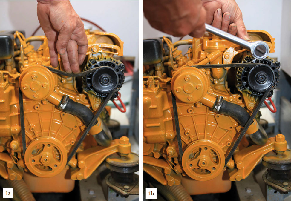
The alternator or dynamo is usually driven by a vee-belt from the crankshaft pulley. The same belt may be used to drive the water pump, so if it is so loose that it slips, the engine will overheat. If it is too tight, it will put a sideways load on the alternator and water pump bearings, causing increased wear and making the belt itself more likely to break.
- a. Once a season or after every 100 hours’ running, inspect the belt for cuts, fraying or oil, and check the tension by pressing firmly on the middle of the longest section of the belt: it should deflect by approximately half an inch.
- b. Adjust the belt if necessary by loosening the bolts that hold the alternator on to the engine, without removing them altogether. Then slacken the bolt holding the supporting bracket to the engine, followed by the one holding the support on to the alternator. Use a short piece of wood such as the handle of a hammer to lever the alternator away from the engine until the belt is tight enough, then tighten all four bolts in the reverse order.
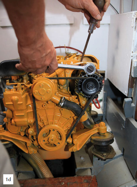
- c. To replace a worn, greasy or broken belt, slacken all the alternator bolts, and swing the alternator so that it is as close to the engine as possible. Use a degreaser such as Gunk or Jizer to clean the pulleys and remove any rust by rubbing with wet-or-dry abrasive or wire wool.
- d. Fit the new belt over the crankshaft pulley, water pump and idler wheel (if there is one), then up to the alternator. Guide it into place as best you can, then use a spanner on the crankshaft pulley to turn the engine while easing the belt into its groove in the alternator pulley. Adjust the belt tension, and check it again after a few hours’ running.
2. LOOKING AFTER YOUR BATTERY
All electrical connections need to be clean and tight, but one of the commonest causes of starting problems is corrosion around the battery terminals.
- a. Slacken the clamp that secures the cables to the battery, and twist it to remove it from the terminal post. Flush off any white or cream-coloured ‘fur’ – acidic crystals of electrolyte – with plenty of very hot water before cleaning the terminals and posts with a wire brush or emery cloth.
- b. Lightly smear the terminal posts with petroleum jelly, and wipe off any excess before replacing the terminal and tightening the clamp. Finally, smear the whole terminal with petroleum jelly to keep out moisture.
- c. Over time, electrolysis and evaporation remove water from the battery, which has to be replaced by pouring distilled water into each cell of the battery until it just covers the top edges of the plates. Some modern batteries have specially designed fillers intended to minimise the loss of electrolyte. Instructions for these are usually given on the battery casing.
- d. If a battery is to be stored or left unused for more than a month or when there is any risk of freezing, it should be left disconnected and fully charged: a voltmeter connected between the + and – terminals should read no less than about 2.1 volts per cell, so a 6-cell, 12-volt battery should show at least 12.5 volts.

References
Adlard Coles Book of Diesel Engines

