The overwhelming majority of engine-driven craft use propellers to convert the power of the engine to useful work. There are plenty of alternatives which may have advantages for specific applications, but propeller systems are good all-rounders that are reasonably cheap, simple, reliable, efficient and easy to use.
They suffer, however, from one potentially significant drawback, which is that a large slowturning propeller is generally more efficient than a small, fast-spinning one. Even on small pleasure craft, where the maximum size of propeller is often limited by hull shape, the optimum shaft speed is usually in the order of 1,000 rpm – only a half or a quarter of the speed of the engine.
Running the engine more slowly isn’t the answer, because you’d just lose most of the power you’ve paid for by buying it in the first place. What you need is something that will reduce the shaft speed but increase its torque (turning effort).
It’s also very useful to be able to reverse the direction of rotation, to provide astern power to stop the boat or make it go backwards, or to fi t counter-rotating propellers on a twin-screw boat. Again, there are alternatives, such as variable-pitch propellers whose blades swivel on the hub, scoop-like deflectors, or even engines that can be stopped and restarted in the opposite direction, but by far the most popular arrangement is a reversing gearbox.
Basic principles
The diagram (Fig 21) shows two gearwheels, whose teeth mesh together so that as one turns, the other has to turn as well. The smaller gear has 9 teeth, so if it is turning at 1,000 rpm, its teeth are moving at 9,000 teeth per minute. The larger wheel is twice the size, and has 18 teeth, so although its teeth must also be moving at 9,000 teeth per minute, that means only 500 rpm. Notice, too, that if the smaller wheel is turning clockwise, the larger wheel must be turning anticlockwise.
Now imagine that you’re using a spanner a foot long to turn the smaller wheel. If you apply an effort of 10 lb to the end of the spanner, you’re applying a torque of 10 lb/ft (10 lb at a radius of 1 ft). The gearwheel is much smaller – let’s say it has an effective radius of 1 in. That means its teeth must be pushing on the teeth of the other wheel with a force equivalent to 120 lb (120 lb at a radius of 1/12 ft = 120 x 1/12 = 10 lb/ft). The larger wheel has an effective radius of 2 in, so a force of 120 lb to its teeth corresponds to a torque of 20 lb/ft (120 x 2/12 = 20 lb/ft).
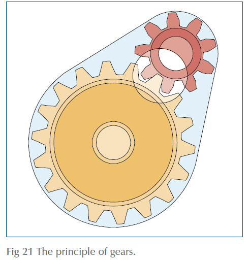
In other words, by using a 9-tooth wheel to drive an 18-tooth wheel, we’ve:
- halved the speed
- doubled the torque, and
- reversed the direction of rotation.
A simple gearbox
Real gearboxes look more complicated, but depend on exactly this principle. In fact, the main difference between the simple gear train in Fig 21 and the Volvo MS2 shown in Fig 22 is that the MS2 uses cone-shaped bevel gears, so that although the input shaft is horizontal, the central driven shaft is vertical.
The motive for this arrangement is that it provides a simple way of achieving a choice of ahead or astern gear.
The bevel gear on the input shaft turns two slightly larger bevel gears that spin freely on the vertical shaft. One is driven by the top of the input gear and the other by the bottom of it, so they rotate in opposite directions, but they are the same size as each other so they turn at the same speed.
Between the two gears is a sliding clutch assembly, shaped like two shallow cones mounted base-to-base on the shaft. Ridges called splines on the shaft and matching grooves in the clutch ensure that it can easily slide up and down, but can’t turn without turning the shaft as well. Moving the gear lever slides the clutch up or down so that one of the cones engages into a matching hollow in one of the spinning gears, which locks that gear on to the shaft.
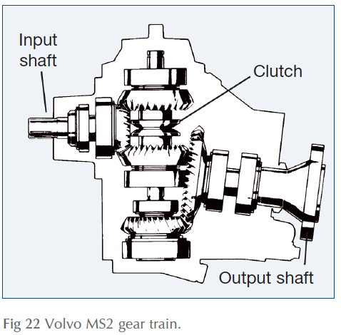
At the bottom of the shaft, a relatively small bevel gear engages with a much larger gear on the output shaft, to give a horizontal output, at a much lower speed of rotation.
Layshaft gearboxes
Although the MS2 and its derivatives are common on Volvo engines up to about 200 hp, it’s somewhat unusual in using a vertical shaft. A more widespread arrangement is the layshaft gearbox, like that shown in Fig 23.
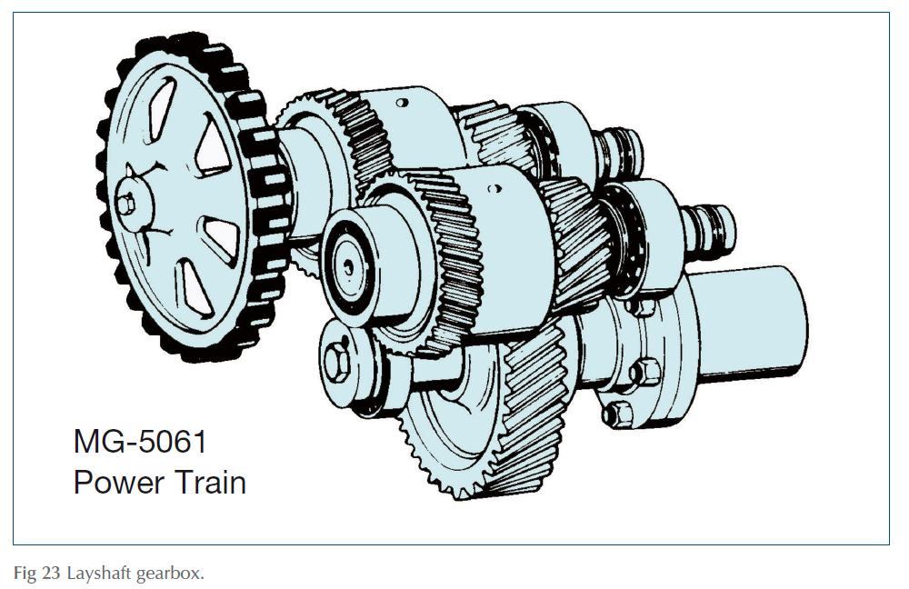
In this case, a small gear on the input shaft turns a larger gear on the layshaft. Like the gears on the vertical shaft of the MS2, this is free to spin around the layshaft, but can be locked on to it by a clutch. If the input shaft is turning clockwise and the clutch is engaged, the layshaft turns anticlockwise and more slowly. At the other end of the layshaft a smaller gear meshes with a large gear on the output shaft, driving the output shaft clockwise and even more slowly.
Astern gear is achieved by a second layshaft. It’s very similar to the first, with two gearwheels, one of which has a clutch that can leave it freespinning or lock it on to the shaft, while the other is constantly in mesh with the output shaft. The key feature about the second layshaft is that it is not driven directly by the input shaft, but by the first layshaft. This means that it’s turning in the opposite direction – so if one clutch is released and the other engaged, the direction of the output shaft will be reversed.
Epicyclic gearboxes
The third alternative – renowned for its smooth operation, but now becoming less popular – is known as the epicyclic gearbox (Fig 24).
The central gearwheel – known as the sun gear – is mounted on the input shaft, driven by the engine. Around it are several smaller planet gears mounted in a rigid cage called the planet holder, while the whole assembly is surrounded by a cylindrical ring gear that looks rather like the hub of a trailer wheel but with teeth machined into its inner surface. The output shaft is coupled directly to the planet holder.
For ahead operation, a clutch is used to lock the planet gears so that they can’t turn. In effect, this means that the input shaft, ring gear, planet holder and output shaft are all locked together so the whole assembly turns as though it were one piece.
For astern gear, the ring gear is locked to the casing, and the planet gears are left free to rotate. If the input shaft turns clockwise, this means that the inner planets have to turn anticlockwise, driving the outer planets clockwise. In order to do this, they have to run anticlockwise around the inside of the ring gear, taking the planet holder – and, of course, the output shaft – around with them.
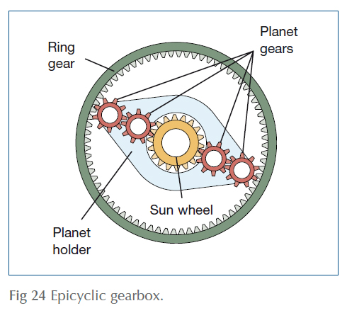
One major snag with this is that although it provides an ahead/astern facility, it can’t offer the reduction in shaft speed that is one of the main reasons for wanting a gearbox in the first place. To do that requires a second gearbox in tandem with the first – adding to the cost, weight, bulk and complexity of the whole unit. The second gearbox is usually another epicyclic unit, but with the important difference that there are no clutches involved, and the output shaft is connected to the ring gear instead of to the planet holder.
In this case, the spinning input shaft coming from the reversing gearbox drives the sun wheel, which makes the planet wheels turn, and they, in turn, drive the ring gear.
Clutches
An important characteristic of all marine gearboxes is that the gears of both drive trains – ahead and astern – are in mesh all the time, and that selection of ahead, astern and neutral is achieved by using clutches to disconnect whichever drive train is not in use.
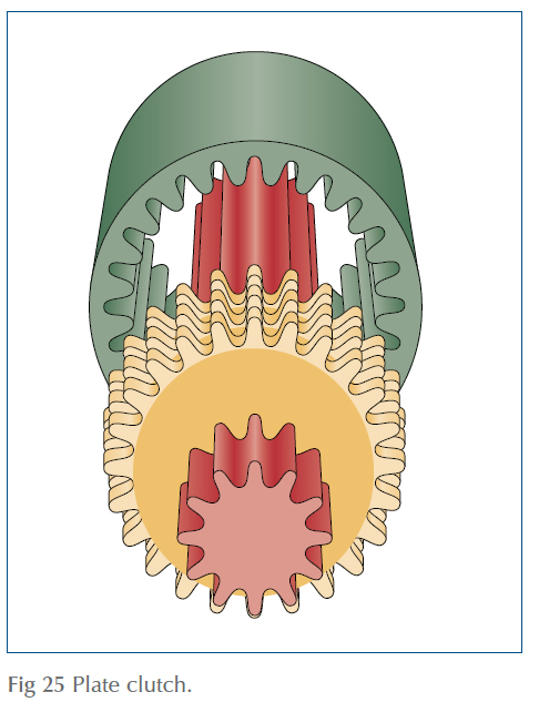
There are two main types of clutches: the cone clutch used in the MS2, and the plate clutch used in most of the others.
The plate clutch consists of a stack of flat friction plates. Some of the plates have internal splines which mesh with matching splines on the shaft, so they have to turn with it. Sandwiched between them are similar plates which are free to spin around the input shaft but have external splines that mesh with splines on the inner surface of the clutch casing – connected to the output shaft. So long as the stack is loose, the two shafts are free to rotate independently of each other. Compressing the stack forces the plates into contact with each other so that they grip and force the two shafts to turn together.
For relatively small engines – up to about 100 hp – a hand-operated lever may be enough to operate either sort of clutch, but bigger engines need more pressure to be applied. This calls for hydraulics, in which a pump built into the gearbox creates hydraulic pressure to force the plates together. All the gear lever has to do is operate a valve, diverting the hydraulic pressure to whichever clutch requires it.
... Things to do
The additives that make modern oils better for your gearbox make them worse for you. Take care to avoid unnecessary or prolonged contact with gearbox oil – new or used.
Only a few teeth of each gearwheel are in mesh with each other at once, and yet the very small surfaces in contact have to transmit the entire power of the engine. When you think about a gearbox in this way, it becomes obvious that the loads involved are very large indeed, and that good lubrication is essential.
Leaks aren’t always obvious, especially if they occur between the engine and gearbox, but an external visual inspection will often reveal minor gearbox faults before they develop into major problems. Look out for loose mounting bolts or control cables, as well as for oil leaks around the shaft, hoses and oil cooler.
- a. If the gearbox shares the engine’s oil, regular oil changes are essential: the acidic by-products of combustion in old engine oil will cause corrosion and rapid wear in the gearbox.
- b. If the gearbox uses its own oil, the level should be checked regularly – ideally every day the engine is used. Some types need the engine to be run before the oil level is checked: consult the manufacturer’s handbook for this, and to find out whether the dipstick has to be screwed in to show the correct level. Gearboxes don’t ‘use’ oil as an engine does, so if the oil level falls it is almost certainly due to leakage.
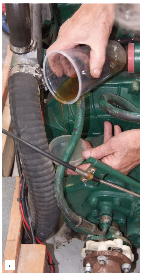
- c. Having dipped the oil, top up if necessary, usually through the dipstick hole or through a separate filler cap.
Different types of gearbox need different types of oil AND THEY DON’T MIX! Check with the manufacturer’s handbook to find out whether your gearbox uses monograde engine oil, gear oil or automatic transmission fluid, and make sure you keep the right stuff on board.
Gearbox dipsticks are often rather awkward to get at, but it’s important to make sure that you put it back exactly the way it came out, or it may come into contact with one of the spinning gears. Ensure that it is pushed fully home or screwed right in.
References
Adlard Coles Book of Diesel Engines

