A few small open workboats still have engine and gearbox controls that can be operated directly by the helmsman, but that simple system is becoming increasingly rare on pleasure craft, where it is very much more common to find some kind of remote control system.
As is often the case on boats, there is no ‘standard’ arrangement: push-pull cables are by far the commonest, but even these are available in several different forms and face competition from hydraulic systems – in which the remote control lever operates a pump connected by pipes to a hydraulic ram that operates the engine controls – and electronic systems that use wires to carry control signals from the wheelhouse to the engine room.
Cable systems
The cables that are used in most systems are rather like those used to work the brakes on a bicycle, with a central control cable inside a tubular outer casing. The casing is fixed at both ends, so that when you pull one end of the inner cable, the other end retracts.
Boats’ control cables are usually very much bigger and more robust than those on a pushbike, but the main difference is that instead of using very fl exible multi-strand wire for the inner cable, marine systems use a single strand of stiff wire that enables them to push as well as pull.
Control heads
It’s easy to see how cables can be used in a twin-lever system, where one lever controls the engine and another operates the gearbox. Pushing the top of the ‘throttle’ lever forwards, for instance, pulls on the cable, which in turn pulls the lever on the engine’s fuel pump.

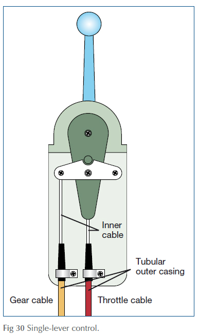
Single-lever systems, in which engine and gearbox are controlled by the same lever, are generally more popular – but are more complicated because they have to achieve a positive gear shift between ahead, neutral and astern, but also offer progressive control of the engine speed.
This is achieved by connecting the ‘throttle’ cable directly to the control lever, while the gear cable is connected to a horizontal seesaw arrangement. A peg sticking out of the throttle lever engages in a notch in the top edge of the seesaw, so that the first few degrees of movement of the control lever is enough to rock the seesaw so that it pulls or pushes on the gear cable. The geometry of the arrangement is such that this first movement of the control lever has virtually no effect on the throttle cable. Once the seesaw has been rocked far enough to engage gear, however, the peg is clear of the slot, and the lever can move further, pulling on the throttle cable without having any more effect on the gear control linkage.
Dual station controls
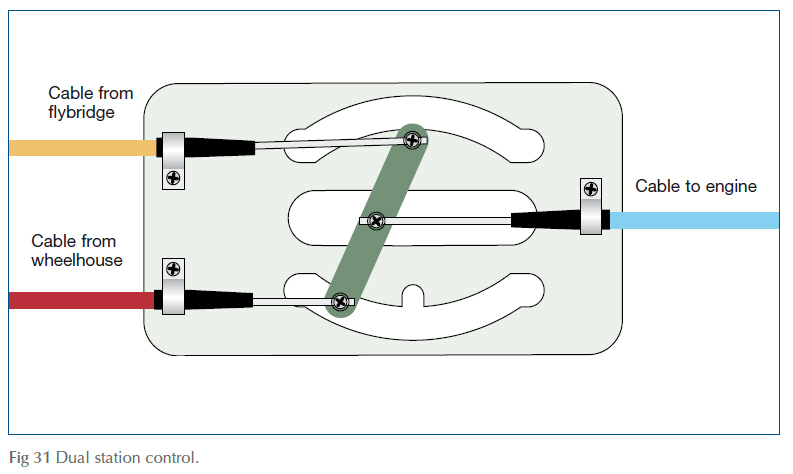
One snag with this system is that it can only be worked with the control lever: pulling or pushing on the other end of the gear cable would have no effect whatsoever. In a boat with only one control station, this is not a problem, but on boats such as motorsailers or flybridge motor cruisers, where the engine may have to be controlled from two different places, it would make the whole system jam up if it were not for a component called a Dual Station (or DS) unit that isolates one control head when the other is in use.
A DS unit is based on a sheet-metal frame with two curved slots cut into it. Bridging the gap between the two slots is a metal bar connected to the incoming cables from the two helm positions and the outgoing cable to the engine. The bar is held in place on the base plate by two metal pegs, which pass through the slots. The clever bit about this arrangement is that the pegs are slightly further apart than the slots: the only reason the pegs can fit into both slots at once is that each slot has a semicircular cut-out. When one peg is nestling in its cut-out, the other peg is free to slide along the slot and vice versa.

If, on a motorsailer, you move the saloon control lever while the cockpit control is in neutral, the cockpit cable’s peg drops into its cutout, allowing the saloon cable to move its end of the bar to push or pull the outgoing cable. When the saloon control is in neutral, any movement of the cockpit control is enough to move the bar so that its ‘saloon’ end drops into its cut-out, leaving the ‘cockpit’ end free to move – with the same effect on the outgoing cable.
Cables
Cable systems are generally reliable so long as they are properly installed in the first place and then receive a certain minimal level of maintenance. It’s worth doing, because if your control system fails, you will almost certainly look foolish (bystanders never believe that a messed-up manoeuvre was caused by mechanical problems), and you may well face serious damage or injury.
When problems do occur, control failure is more often due to problems with the cable, rather than to the control units themselves:
- Internal corrosion, caused by water getting in through splits in the outer cable, can jam the inner cable.
- Wear on the inner surfaces of the outer cable allows the inner cable to slop from side to side, producing excessive backlash (free play) on the cable end: on a gear cable this may mean that there is not enough controlled movement to operate the gear lever properly.
- Bent or corroded end rods make operation stiff and may eventually lead to the inner cable stretching: again, this is particularly serious in the gear cable.
- Worn, corroded or disconnected end fittings. The split pins that secure the cable to the gearbox and fuel pump are so thin that they are particularly prone to corrosion, but look out too for the clamping arrangements that hold the outer cable in place.
- Poorly designed cable runs can make controls stiff from the outset, and give rise to a lot of backlash. Over time, this gets worse, as the bends cause increased wear and tear inside the cable: ideally cables should be dead straight, with no long sweeping bends or bends tighter than about 8 in (20 cm) radius.
... Things to do
- a. Periodically – about once a season, but more often in exposed locations – inspect the cable end fittings for wear and corrosion. Replace split pins with new ones if they are corroded, or if they have been removed for any reason.
- b. With the inner cable in its fully extended position, lightly grease the exposed part with a non-graphite grease.
- c. Clean and re-grease the moving parts of control heads and DS units. Inspect the cable run, looking for splits or wear in the outer plastic sheath – often given away by rust streaks.

References
Adlard Coles Book of Diesel Engines

