Flywheel connection
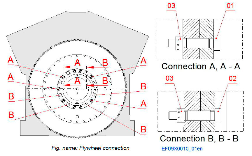
The flywheel is connected to the crankshaft with fitting screws and special screws.
The amount of fitting screws is dependent on the engine configuration.
System components
- 01 Fitting screw
- 02 Screw
- 03 Nut
Flywheel indicator
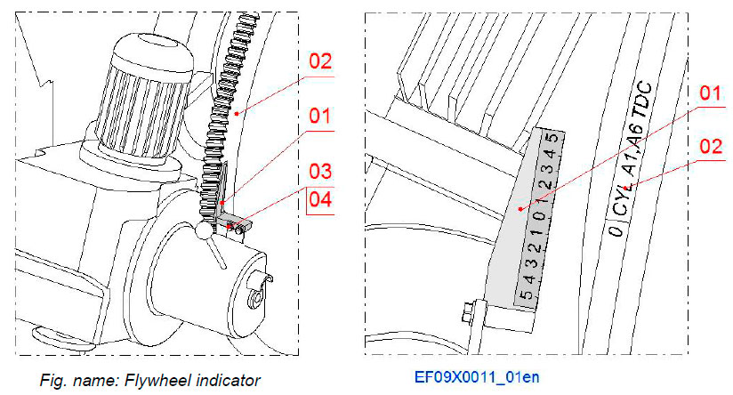
The flywheel indicator with its bracket is mounted on the turning device.
Components
- 01 Flywheel indicator
- 02 Flywheel with graduation
- 03 Screw
- 04 Washer
Flexible coupling
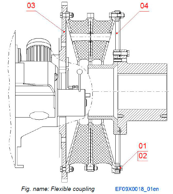
The power transmission of an engine is accomplished through a flexible coupling mounted on the flywheel.
The crankshaft is equipped with an additional shield bearing at the driving end. Therefore a rather heavy coupling be mounted on the flywheel without requiring the use of intermediate bearings.
Components
- 01 Screw
- 02 Washer
- 03 Flywheel
- 04 Coupling
Resilient mounting
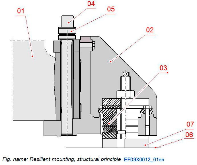
STRUCTURAL PRINCIPLE
The resilient mounting arrangement is according to the proven concept used on earlier Wärtsilä 46 engines.
The engine is mounted onto the ship foundation with rubber elements.
Components
- 01 Engine
- 02 Engine foot
- 03 Resilient element
- 04 Screws
- 05 Round nut
- 06 Foundation
- 07 Adjusting piece
LAYOUT ON ENGINE
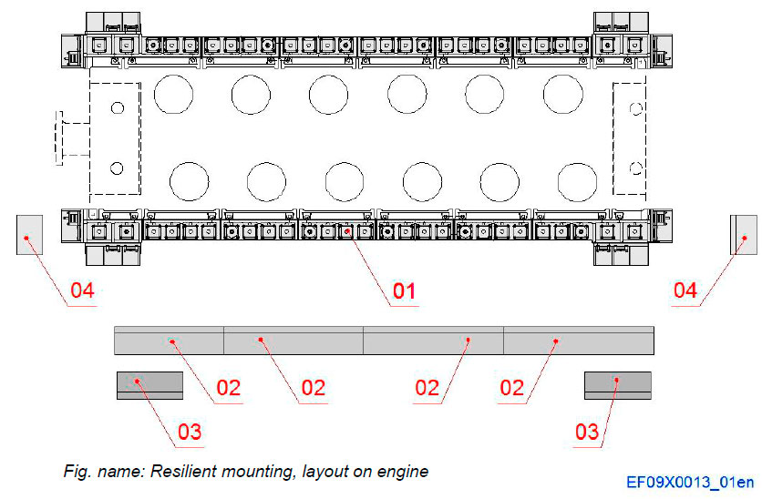
In order to reduce vibrations and structure transmitted noise the engine is flexibly mounted. The engine block is so rigid that no intermediate base frame is necessary, but the rubber mounts are fixed to the engine feet by means of a rail. The advantage of the vertical type mounting is easier alignment.
The material of the mounts is natural rubber, which have superior vibration technical properties. The rubber mounts are prone to damage by mineral oil and are therefore protected against dripping and splashing by means of covers.
Components
- 01 Resilient mounting
- Rubber elements - 02 Protection plates
- Vertical elements - 03 Protection plates
- Horizontal elements, side - 04 Protection plates
- Horizontal elements, end
RUBBER ELEMENTS
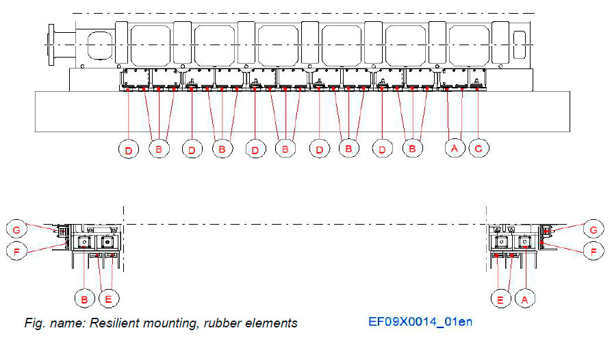
The figure shows the location of the different rubber elements.
The A, B, C and D elements are vertical dampers. The E, F and G elements are horizontal dampers.
Components
- A Rubber element
- B Rubber element
- C Rubber element
- D Rubber element
- E Rubber element
- F Rubber element
- G Rubber element
RUBBER ELEMENTS, VERTICAL
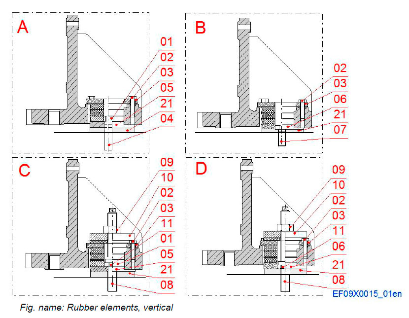
The amount of the different elements depends on the engine configuration.
- A - Element
- B – Element
- C – Element
- D - Element
Components
- 01 Rubber element
- 02 Screw
- 03 Washer
- 04 Screw
- 05 Plate
- 06 Rubber element
- 07 Hexagon bolt
- 08 Screw M36
- 09 Nut
- 10 Rubber element
- 11 Nut
- 21 Adjusting piece
RUBBER ELEMENTS, HORIZONTAL
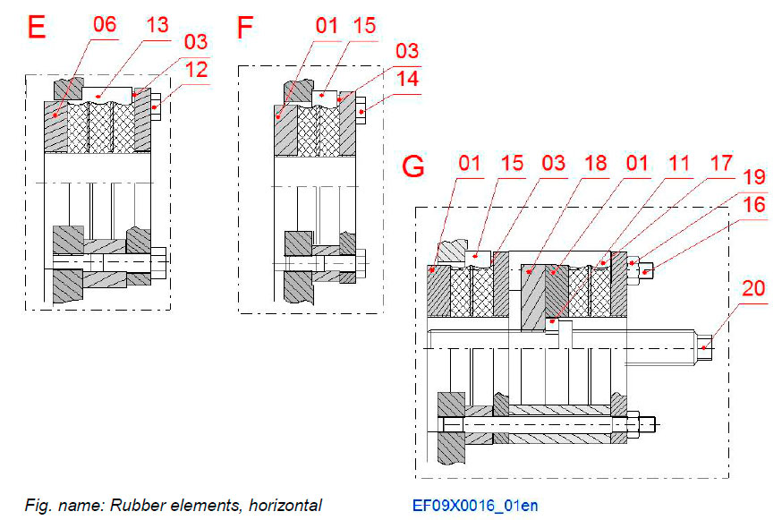
The amount of the different elements depends on the engine configuration.
- E - Element
- F - Element
- G - Element
Components
- 01 Rubber element
- 03 Washer
- 06 Rubber element
- 11 Nut
- 12 Screw
- 13 Distance sleeve
- 14 Screw
- 15 Distance sleeve
- 16 Stud
- 17 Distance sleeve
- 18 Plate
- 19 Nut
- 20 Screw
Engine identification - Signs
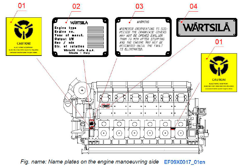
NAME PLATES ON THE ENGINE MANOEUVRING SIDE
- 01 Welding caution label
- 02 Engine type plate
- 03 Overheating warning plate
- 04 Brand name plate
NOTE! Overheating warning plate and welding caution label are also found on the rear side of the engine.
Литература
www.wartsila.com

