Content
- Intake and exhaust system arrangement - internal
- Intake and Exhaust system on engine
- Charge air system
- Charge air supply from receiver to cylinder head
- Water cleaning device for turbocharger
- Principal scheme for turbine washing valve unit
- Washing valve unit
- Washing system for turbocharger
- Cleaning nozzles for charge air system
- Intake & Exhaust manifolds
- Waste gate system
- Waste gate valve
- Insulations for charge air supply lines and cooler
- Insulation for exhaust manifold
- Insulation between exhaust manifold and charge air receiver
- Insulation for exhaust inlet to turbocharger
- Insulation for turbocharger
- Insulation panels for exhaust inlet to turbochargers
- Insulation between cylinder head and insulation box
- Insulation for waste gate system
Intake and exhaust system arrangement - internal
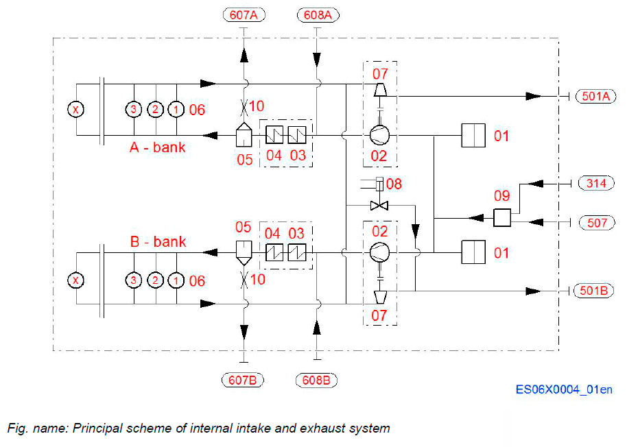
System components
- 01 Air filter
- 02 Compressor
- 03 Charge air cooler (HT)
- 04 Charge air cooler (LT)
- 05 Water mist catcher
- 06 Cylinders
- 07 Turbine
- 08 Waste gate valve
- 09 Cleaning device for turbocharger
- 10 Orifice for condensate water outlet
Pipe connections
- 314 Air supply to compressor and turbine cleaning unit
- 501A Exhaust gas outlet, A-bank
- 501B Exhaust gas outlet, B-bank
- 507 Cleaning water to turbine and compressor
- 607A Condensate water after charge air cooler, Abank
- 607B Condensate water after charge air cooler, Bbank
- 608A Cleaning water to charge air cooler, A-bank
- 608B Cleaning water to charge air cooler, B-bank
Intake and Exhaust system on engine
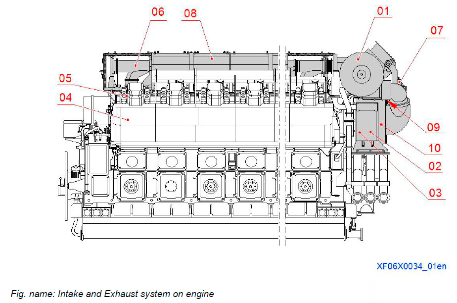
The intake and exhaust system channels delivers the compressed air to the combustion chamber and carries the exhaust gases out from the combustion chamber to exhaust manifold.
The intake and exhaust system can be split up into an intake section including the charge air system and an exhaust section including the exhaust system.
System components
- 01 Turbocharger
- 02 Charge air cooler
- 03 Water mist catcher
- 04 Charge air receiver (in engine block)
- 05 Charge air supply pipe
- 06 Exhaust manifold
- 07 Waste gate valve
- 08 Insulation box
- 09 Washing device for turbocharger
- 10 Washing device for charge air cooler
Charge air system
TURBOCHARGER
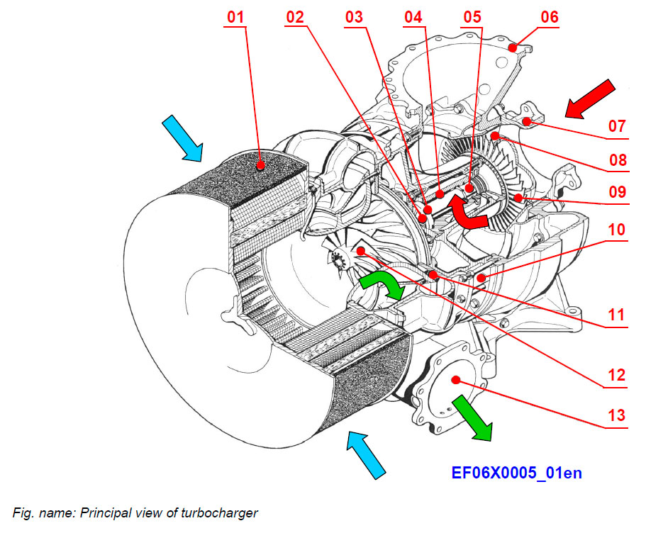
The turbochargers are driven by the exhaust gases coming from the cylinders through the opened exhaust valves. The compressor is driven by the turbine. The energy of the exhaust gases are used to compress the intake air of ambient pressure to a higher level. The charged air enlarges the air quantity fed into the combustion space and thus makes it possible to burn a bigger amount of fuel in the cylinder space.
The combustion air is taken outside of engine to the compressor side of the turbocharger. Passing through the compressor side, the air pressure and density are increasing as well as the temperature. The hot air is cooled down in the charge air coolers.
System components
- 01 Filter silencer
- 02 Radial plain bearing
- 03 Axial thrust bearing
- 04 Bearing bush
- 05 Radial plain bearing
- 06 Gas outlet casing
- 07 Gas inlet casing
- 08 Nozzle ring
- 09 Turbine wheel
- 10 Bearing casing
- 11 Diffuser
- 12 Compressor wheel
- 13 Air outlet casing
BASIC SETTINGS OF TURBOCHARGING
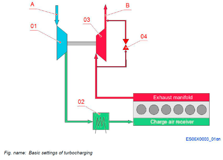
System components
- 01 Compressor
- 02 Charge air cooler
- 03 Turbine
- 04 Waste gate valve
Connections
- A Air intake
- B Exhaust outlet
Power Plant application
- Waste gate: YES
- By pass: NO
Marine diesel electric:
- Waste gate: YES
- By pass: NO
The ambient air is compressed in the TC compressor. The compressed air passes through two 2-stage air coolers. After the coolers the water condensate is separated from the charged air in the water mist catchers. The charge air system is in addition equipped with a two nozzles for water washing of the charge air coolers.
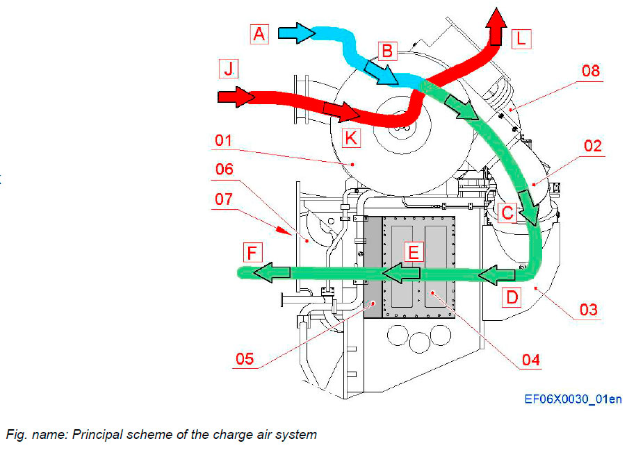
System components
- 01 Turbocharger
- 02 Charge air pipe
- 03 Air inlet box
- 04 Charge air cooler
- 05 Water mist catcher
- 06 Bracket and connecting box to engine block
- 07 Charge air receiver in engine block
- 08 Waste gate pipe to exhaust outlet
Inlet and charge air flow
- A Ambient air
- B Air to compressor inlet
- C Charge air to inlet box
- D Charge air to charge air coolers
- E Charge air to water mist catchers
- F Charge air to charge air receiver
Exhaust gas flow
- J Exhaust outlet from cylinder
- K Exhaust to TC turbine
- L Exhaust outlet to stack
DESCRIPTION OF CHARGE AIR COOLERS
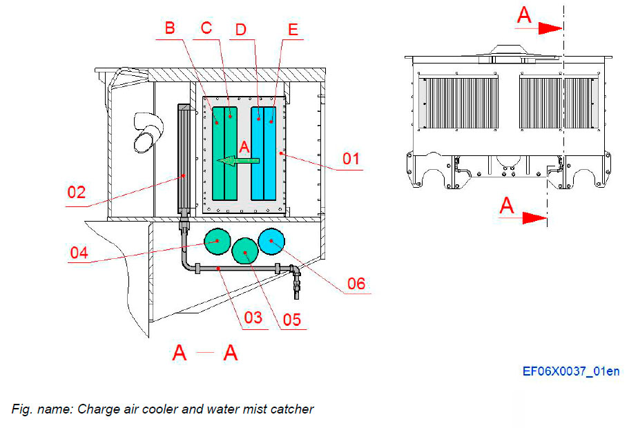
The engine is equipped with two charge air coolers to cool down the compressed and heated air after the turbochargers. The charge air coolers are of insert type and mounted in a common frame.
The charge air temperature is kept at the correct level by the flow of the high temperature and low temperature cooling water. The cooling water is circulated through the tubes. The charge air passes between the fins on the outside of the tubes. Additionally there are two water mist catchers, one for each cooler, mounted after the coolers in the same frame, which enables to reduce NOx emission values.
Components and connections
- 01 Charge air cooler
- 02 Water mist catcher
- 03 Drain pipes for condense water
Connections
- A Air flow
- B LT water inlet
- C LT water outlet
- D HT water inlet
- E HT water outlet
Charge air supply from receiver to cylinder head
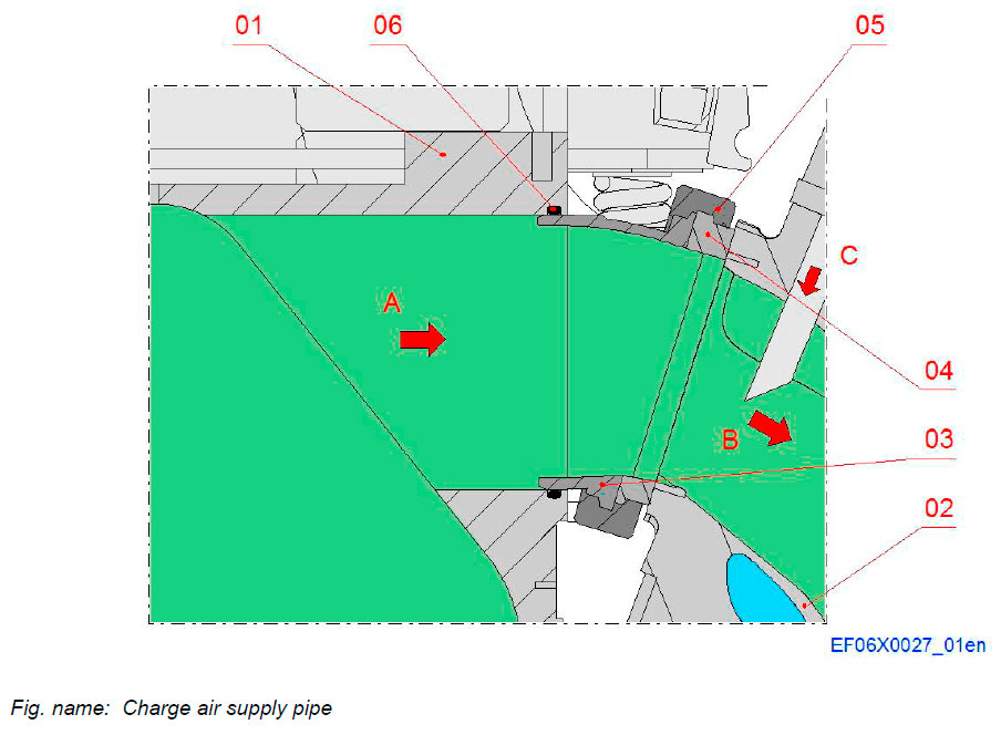
The charge air flows from the receiver in the engine block to the cylinder heads trough The charge air supply pipe and channel in cylinder head.
Components
- 01 Charge air receiver
- 02 Cylinder head
- 03 Air supply pipe
- 04 Connection flange
- 05 Clamping ring
- 06 O-ring
Connections
- A Charge air supply from engine block
- B Charge air supply to cylinder head
- C Gas feed connection
Water cleaning device for turbocharger
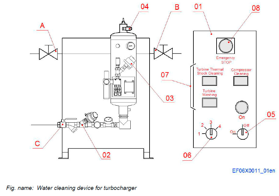
CLEANING WATER PRESSURE INCREASE UNIT
The cleaning pressure increase unit is located outside of the engine. It consists of a water supply unit and of an electrical control panel.
The washing sequences are controlled (operated) by the control unit and are freely programmable with parameters.
System components
- 01 Electrical control panel
- 02 Control valve of water supply
- 03 Control valve of air supply
- 04 Ventilation valve
Function buttons
- 05 ON/OFF key
- 06 Selector switch
- 07 Control switches of cleaning procedures
- 08 Emergency STOP button
System connections
- A Shut-off valve of air supply
- B Shut-off valve before valve washing unit
- C Shut-off valve of input unit
Principal scheme for turbine washing valve unit
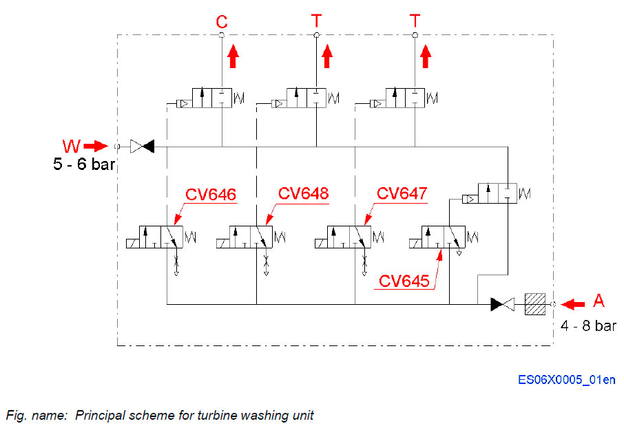
System components
- CV646 CS – valve actuator
- CV647 TS – valve 1
- CV648 TS – valve 2
- CV645 Air – valve actuator
System connections
- A Air, pressurized (4 - 8 bar)
- W Water from cleaning device
- water pressure (5 - 6 bar)
- C Compressor cleaning
- T Turbine cleaning
Washing valve unit
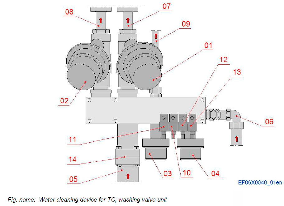
Components
- 01 TS valve 1
- 02 TS valve 2
- 03 CS valve
- 04 Air valve
- 05 Water inlet
- 06 Air inlet
- 07 Water pipe to turbine 1
- 08 Water pipe to turbine 2
- 09 Water pipe to compressors
- 10 TS valve actuator 1
- 11 TS valve actuator 2
- 12 CS valve actuator
- 13 Air valve actuator
- 14 Non-return valve
Washing system for turbocharger
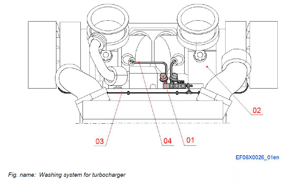
The washing system equipment mounted on the engine consists of the washing valve unit and the pipe systems for compressor and turbine washing.
The washing procedure is activated and controlled with equipment located outside the engine.
- Components located on the engine
- The turbocharger valve washing unit (one for each turbocharger) consisting of:
- Control valves
- Actuator valves and
- Pipe system
Systems components:
- 01 Valve unit for water cleaning device
- 02 Turbocharger
- 03 Pipe line for compressor washing
- 04 Pipe line for turbine washing
Cleaning nozzles for charge air system
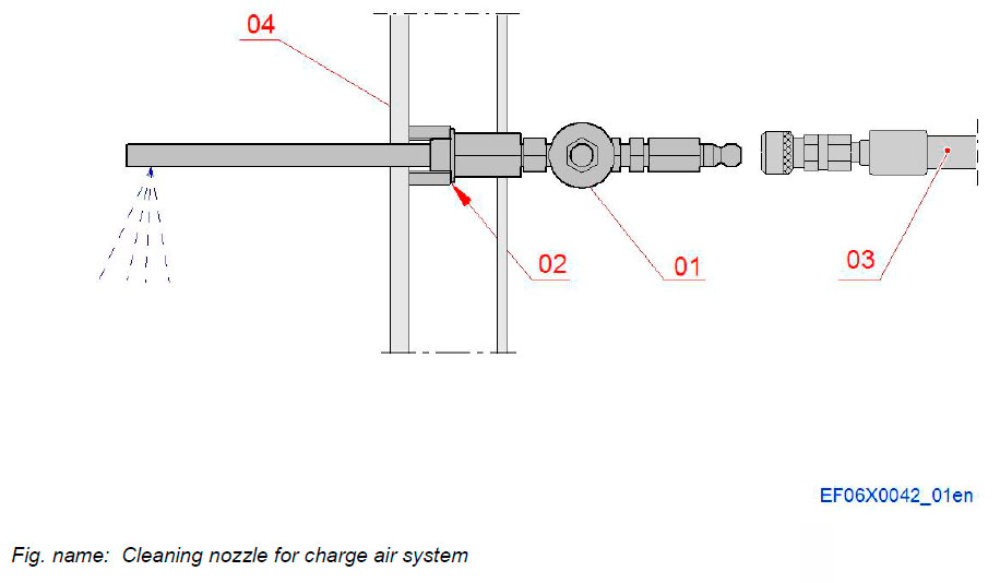
The charge air system is equipped with a two nozzles for water washing of the charge air coolers.
The nozzles are mounted in such a position that the spraying direction is opposite to the air flow.
System components
- 01 Nozzle with valve and adapter
- 02 Sealing ring
- 03 Hose with quick coupling
- 04 Charge air cooler housing
Intake & Exhaust manifolds
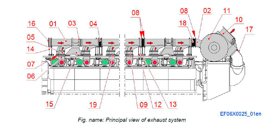
- The exhaust manifold is divided into modules.
- Each module contains of one exhaust pipe (01) connected to the cylinder heads with bellows (05) and exhaust pipes (06).
- The exhaust pipe modules are provided with flexible bellows (04) on each end to avoid thermal deformations.
- The bellows are fitted to the pipes with screws and nuts.
System components
- 01 Exhaust pipe
- 02 Exhaust pipe
- 03 Bracket
- 04 Bellows
- 05 Bellows
- 06 Exhaust pipe
- 07 Sealing ring
- 08 Sealing ring
- 09 Support plate
- 10 Exhaust pipe
- 11 Turbocharger
- 12 Support
- 13 Support arm
- 14 Support
- 15 Support
- 16 Blank flange
- 17 Waste gate system
- 18 Bellows
- 19 Insulation
Intake & Exhaust manifolds
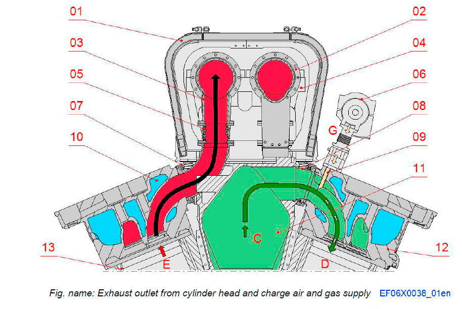
System components
- 01 Exhaust pipe insulation
- 02 Exhaust pipe
- 03 Exhaust outlet from cylinder
- 04 Exhaust pipe support
- 05 Exhaust bellows
- 06 Gas feed pipe
- 07 Clamping ring
- 08 Air inlet pipe to cylinder
- 09 Gas injection nozzle
- 10 Cooling water
- 11 Charge air receiver
- 12 Cylinder head
- 13 Cylinder liner
Connections
- C Charge air from receiver
- E Exhaust gas out
- D Gas and air mix into cylinder
- G Gas into cylinder head
Waste gate system
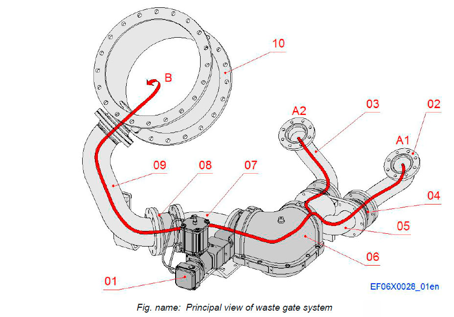
The waste gate system consists of the waste gate unit and an exhaust pipe system with bellows and protection covers. The waste gate unit is mounted near the turbochargers above the charge air cooler housing.
The waste gate valve is working as a regulator and adjusts the airfuel ratio to the correct value by opening to limit the exhaust gas flow to the turbochargers. The waste gate valve thus reduces the charge air pressure and firing pressure to suitable level in whole scale of the power output range.
The waste gate system is controlled by WECS. When engine is running with gas mode the waste gate system operates as active and with diesel mode mainly as passive when the is valve closed.
System components
- 01 Waste gate valve
- 02 Piping from TC 1 turbine inlet
- 03 Piping from TC 2 turbine inlet
- 04 Bellows
- 05 Branch pipe to waste gate valve
- 06 Pipe to waste gate valve
- 07 Pipe from waste gate valve
- 08 Bellows
- 09 Pipe to stack
- 10 Exhaust pipe to stack from TC 2
Connections
- A1 Exhaust gas from TC 1 turbine inlet
- A2 Exhaust gas from TC 2 turbine inlet
- B Exhaust outlet to stack from TC 2
Waste gate valve
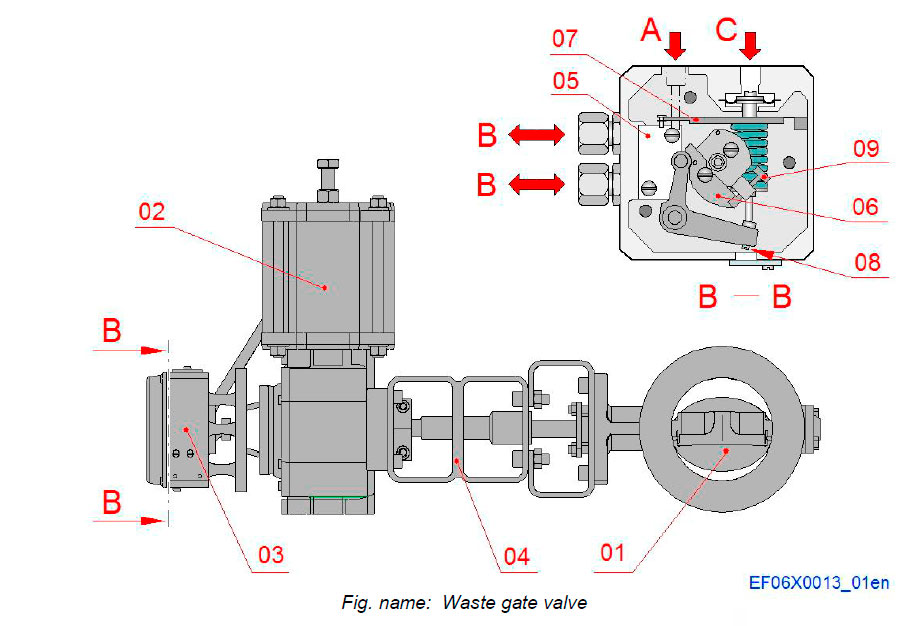
The waste gate valve unit is situated in a pipeline between exhaust inlet to TC and exhaust outlet to stack. The valve is controlled electronically and operated pneumatically.
The waste gate control system gets compressed air from the instrument air system.
System components
- 01 Butterfly valve
- 02 Actuator (pneumatic power cylinder)
- 03 Positioner
- 04 Cooling extension
- 05 Positioner pilot valve
- 06 Lever
- 07 Cam
- 08 Adjusting screw
- 09 Adjusting screw
Connections
- A Control air from the system
- B Connections to and from the actuator
- C Control air from I/P converter
Insulations for charge air supply lines and cooler
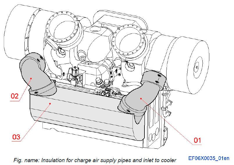
The Insulations for the charge air supply lines and the charge air cooler consists of insulation piping, sealing covers and plate frames insulated with super wool. The super wool insulations are covered with glass fibre cloths.
System components
- 01 Insulation for charge air pipe 1
- 02 Insulation for charge air pipe 2
- 03 Insulation for air inlet to coolers
Insulation for exhaust manifold
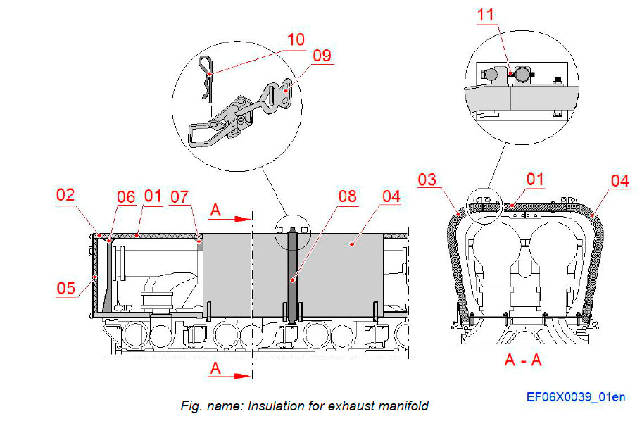
The Insulation for the exhaust manifold consists of insulation segment spit up in parts that can easily be dismantled for maintenance of the exhaust manifold.
The insulation segments are supported by frames. The insulation sections are fixed to each others with fixing bands.
The fixing bands are joint together with tensioning bars. The upper and side segments are kept together with locking latches.
System components
- 01 Insulation, upper segment
- 02 Insulation, upper end segment
- 03 Insulation, side segment
- 04 Insulation, side segment
- 05 Insulation, end segment
- 06 Frame
- 07 Frame
- 08 Fixing band
- 09 Tensioning bar
- 10 Cotter pin
- 11 Locking latch
Insulation between exhaust manifold and charge air receiver
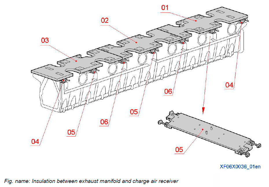
The insulation between charge air receiver and exhaust manifold consist of insulating bottom segment. The bottom segments are kept in place with connection pieces. The amount and type of the insulation segment and the connection pieces is depends on the engine configuration.
System components
- 01 Insulation, bottom segment
- 02 Insulation, bottom segment
- 03 Insulation, bottom segment
- 04 Connection piece
- 05 Connection piece
- 06 Connection piece
Insulation for exhaust inlet to turbocharger
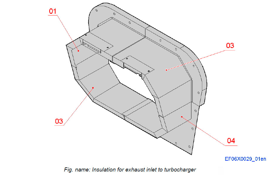
The insulation cover between the exhaust manifold insulation box and the turbochargers consists of four insulation parts. These parts are mounted in place with screws.
System components
- 01 Exhaust pipe insulation, upper part, left
- 02 Exhaust pipe insulation, upper part, right
- 03 Exhaust pipe insulation, lower part, left
- 04 Exhaust pipe insulation, lower part, right
Insulation for turbocharger
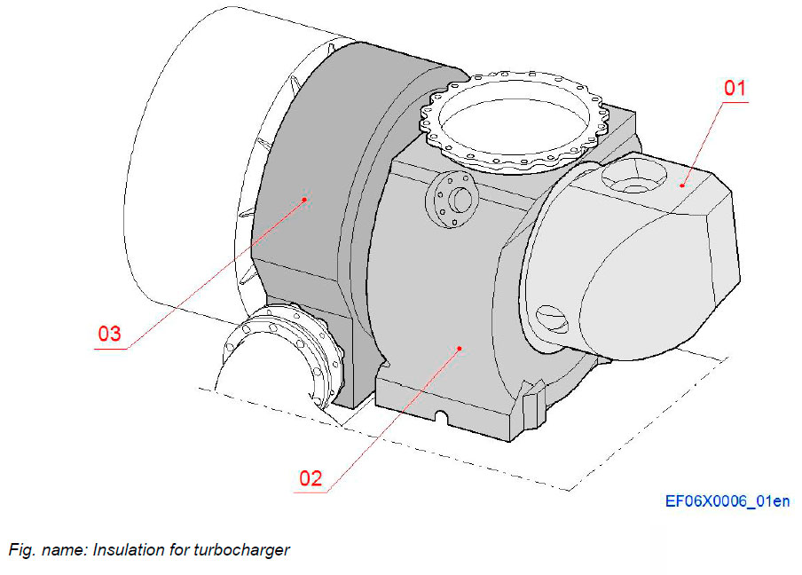
All parts of the turbochargers are covered with insulation boxes.
The figure shows the turbocharger in B-bank.
System components
- 01 Insulation for exhaust inlet to turbine
- 02 Insulation for turbine
- 03 Insulation for compressor
Insulation panels for exhaust inlet to turbochargers
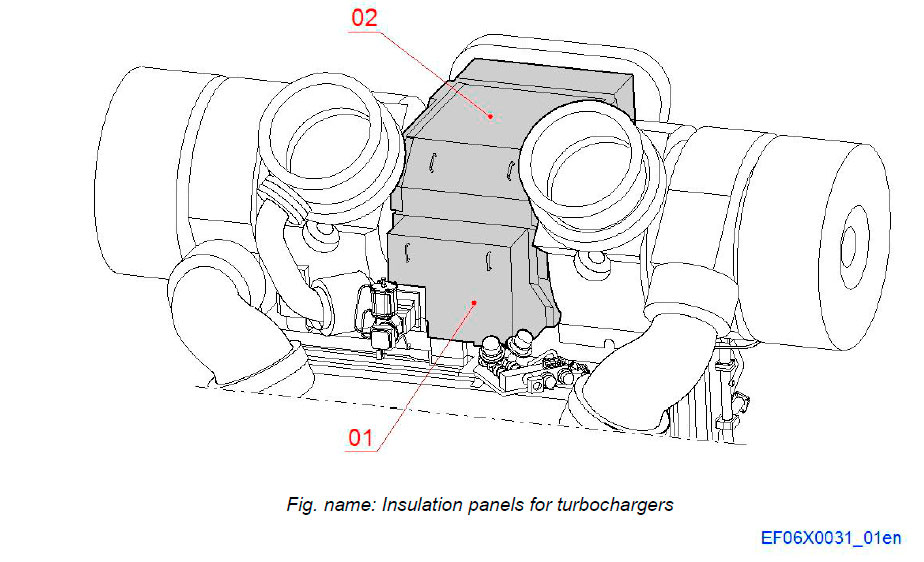
The hot exhaust inlet side of the turbochargers are in addition to the insulation covers also protected with insulation panels.
System components
- 01 Insulation panel
- 02 Insulation panel
Insulation between cylinder head and insulation box
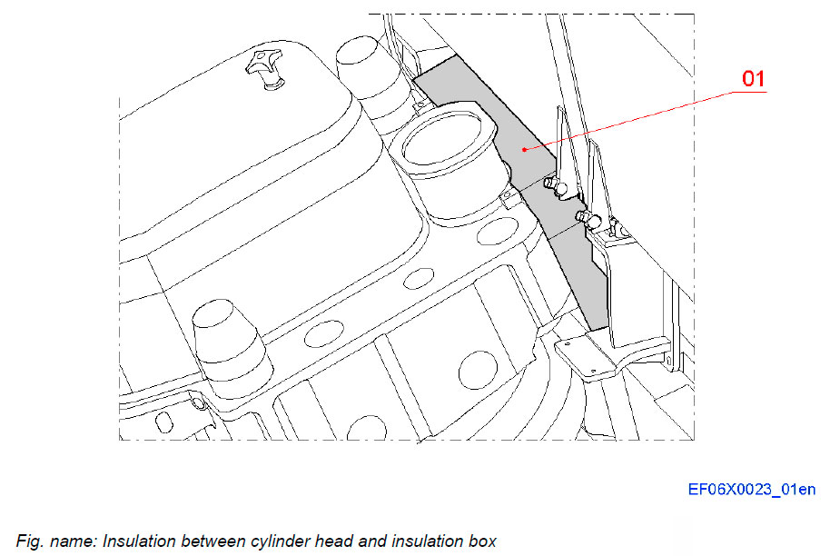
The insulation between the cylinder head and the main insulation box for the exhaust manifold consists of a steel plate cover insulated with super wool insulation which is covered with glass fibre cloths. The insulation covers the flange of the exhaust bend.
System components
- 01 Insulation for exhaust bend
Insulation for waste gate system
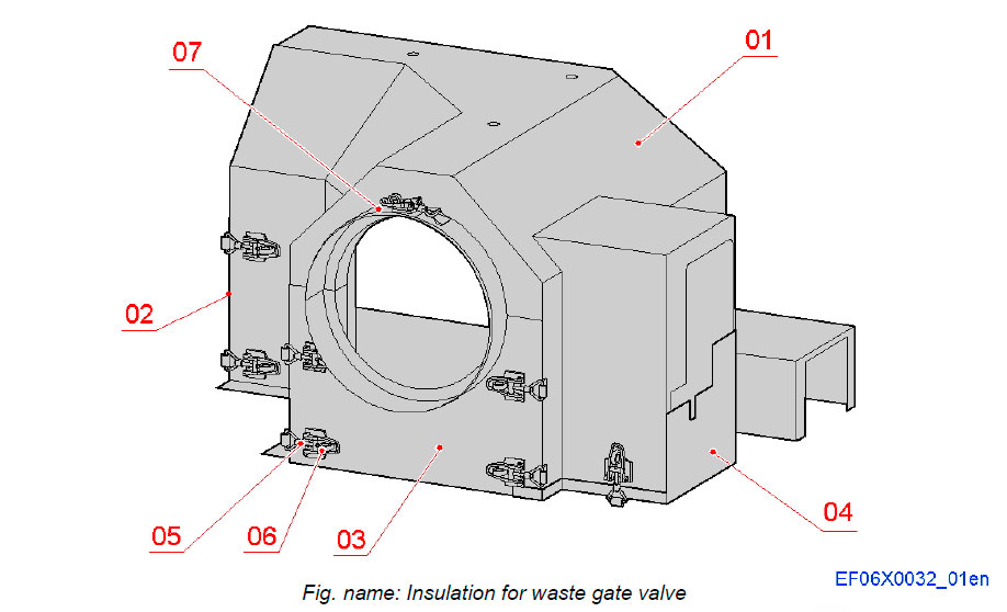
WASTE GATE VALVE
The insulation box assembly for the waste gate system consists of one insulation box and three end plates sections. These sections are attached to each others with tension bar locking latches. The tensioning bars are secured with spring cotters. The insulation covers the waste gate valve and the exhaust pipe between connection pipe branch from exhaust manifold and outlet to stack.
System components
- 01 Insulation
- 02 End piece
- 03 End plate
- 04 End piece
- 05 Tensioning bar
- 06 Spring cotter
- 07 Clamping band
WASTE GATE PIPING
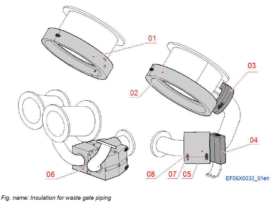
The insulation for the waste gate pipe system consists of insulation boxes as shown in the figure. These insulation boxes are split up into sections for easy dismantling for maintenance work. The box sections are attached to each others with tension bar locking latches. The tensioning bars are secured with spring cotters.
The insulated parts covers the branch pipe from turbochargers to waste gate valve and the bellows on the exhaust pipe between the waste gate valve and the connection to the outlet to stack.
System components
- 01 Insulation, TC1 outlet to stack
- 02 Insulation, TC2 outlet to stack
- 03 Insulation, Bellows, waste gate connection
- 04 Insulation, Exhaust pipe support
- 05 Insulation, Bellows DN150
- 06 Insulation, Bellows
- 07 Tensioning bar
- 08 Spring cotter
Литература
www.wartsila.com

