Starting air system arrangement - Internal
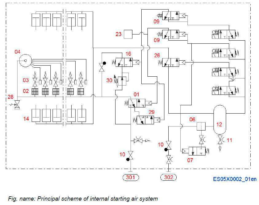
The engine is started by means of compressed air. Control air is needed for timing the operation of pneumatically operated starting valves and fuel injection pump pneumatic stop cylinders.
System components
- 01 Main starting valve
- 02 Flame arrester
- 03 Starting air valve in cylinder head
- 04 Starting air distributor
- 06 High pressure air filter
- 07 Water outlet valve
- 09 Blocking valve for turning gear
- 10 Non-return valve
- 11 Drain valve
- 12 Air container
- 14 Pneumatic stop cylinder
- 16 Slow turning valve
- 23 Booster servomotor for governor
- 26 Stop valve
- 28 Safety valve
- 29 Drain valve
- 30 Pressure regulator
Connections
- 301 Starting air inlet
- 302 Control air inlet
Starting air system on engine
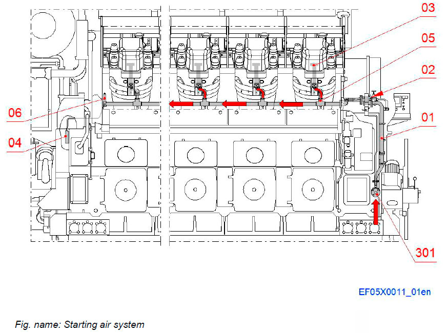
Pressurised air to the engine is supplied through the starting air delivery piping (01) to the main starting valve (02).
The start is performed by direct injection of air into the cylinders through the starting valves in cylinder heads (03), which are opened by a minor part of the air volume being diverted to the correct cylinder head by the starting air distributor (04).
System components
- 01 Starting air delivery piping
- 02 Main starting valve
- 03 Starting valve in cylinder head
- 04 Starting air distributor
- 05 Flame arrester
- 06 Safety valve
Connections
- 301 Starting air inlet
STARTING AIR DEVICES ON ENGINE (A-BANK)
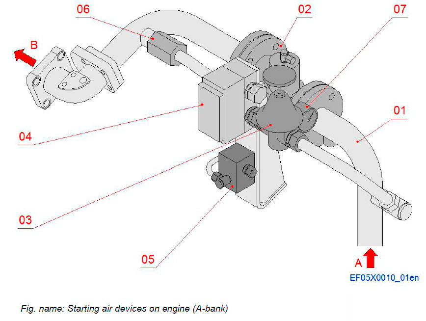
System components
- 01 Starting air delivery piping
- 02 Main starting valve
- 03 Pressure regulator
- 04 Slow turning valve
- 05 Drain valve
- 06 Non-return valve
- 07 Pressure gauge
Connections
- A Starting air inlet to the engine
- B Air to starting air delivery valve in cylinder head
Main starting valve
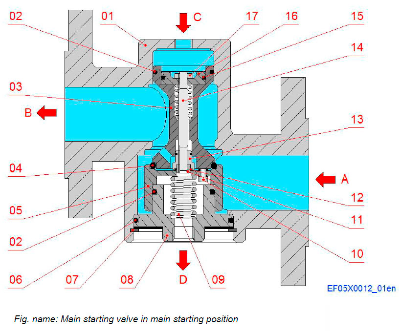
The main starting valve controls the starting air flow to the starting valves in cylinder heads during the starting procedure.
Components
- 01 Housing
- 02 O-ring
- 03 Spool
- 04 O-ring
- 05 Spool cap
- 06 O-ring
- 07 Retaining ring
- 08 Spool stop
- 09 Spring
- 10 Screw
- 11 Vent plug nut
- 12 O-ring
- 13 Vent plug
- 14 Vent stem
- 15 O-ring
- 16 Vent piston
- 17 Nut
Connections
- A Starting air inlet
- B Starting air to cylinder heads and starting air distributor
- C Control air inlet (main starting)
- D Air vent
Starting air delivery valve in cylinder head
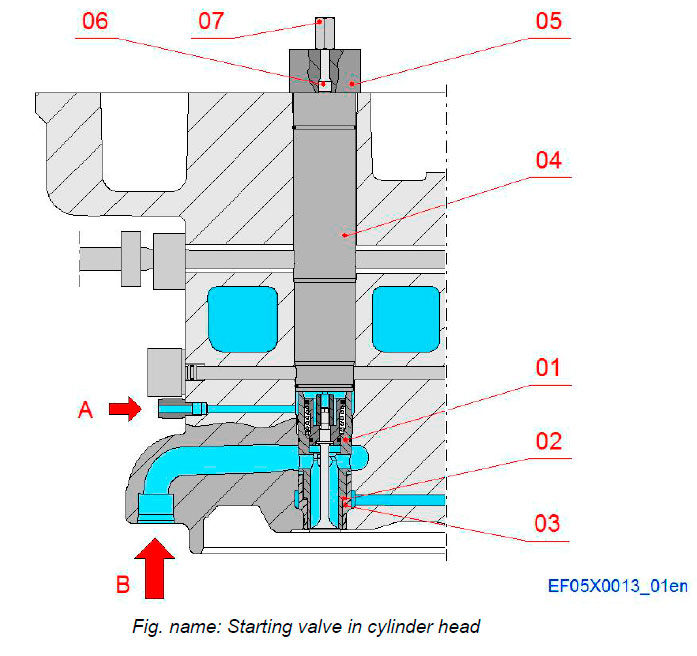
The starting air delivery valve opens and closes the starting air supply to the cylinders.
Control air coming from the starting air distributor controls the opening and closing of the valve during the starting procedure.
Normally the valve is closed.
Components
- 01 Starting air delivery valve
- 02 Sealing ring
- 03 Sleeve
- 04 Extension
- 05 Yoke
- 06 Stud
- 07 Nut
Connections
- A Control air
- B Starting air
STARTING AIR DELIVERY VALVE
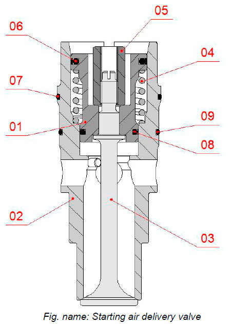
Components
- 01 Piston
- 02 Housing
- 03 Spindle
- 04 Compression spring
- 05 Locking nut
- 06 Slide o-ring
- 07 O-ring
- 08 Slide o-ring
- 09 O-ring
Dummy in B-bank cylinder head
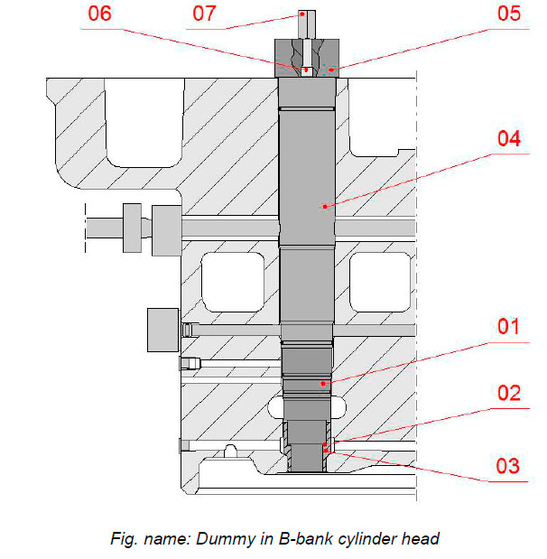
There are no starting air delivery valves in the B-bank cylinder heads. A dummy has been installed instead.
Components
- 01 Dummy
- 02 Sealing ring
- 03 Sleeve
- 04 Extension
- 05 Yoke
- 06 Stud
- 07 Nut
Starting air distributor
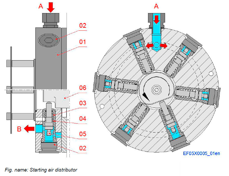
The starting air distributor controls the opening sequence and timing of the starting valves in cylinder heads.
The starting air distributor is driven directly from the camshaft. There is one piston type valve for controlling each starting air delivery valve mounted in the cylinder head. The valves are situated radially in the housing of the distributor.
Components
- 01 Housing
- 02 Screw plug
- 03 Bush
- 04 Spring
- 05 Slide
- 06 Starting cam
Connections
- A Control air inlet
- B Control air to starting air delivery valve
Flame arrester
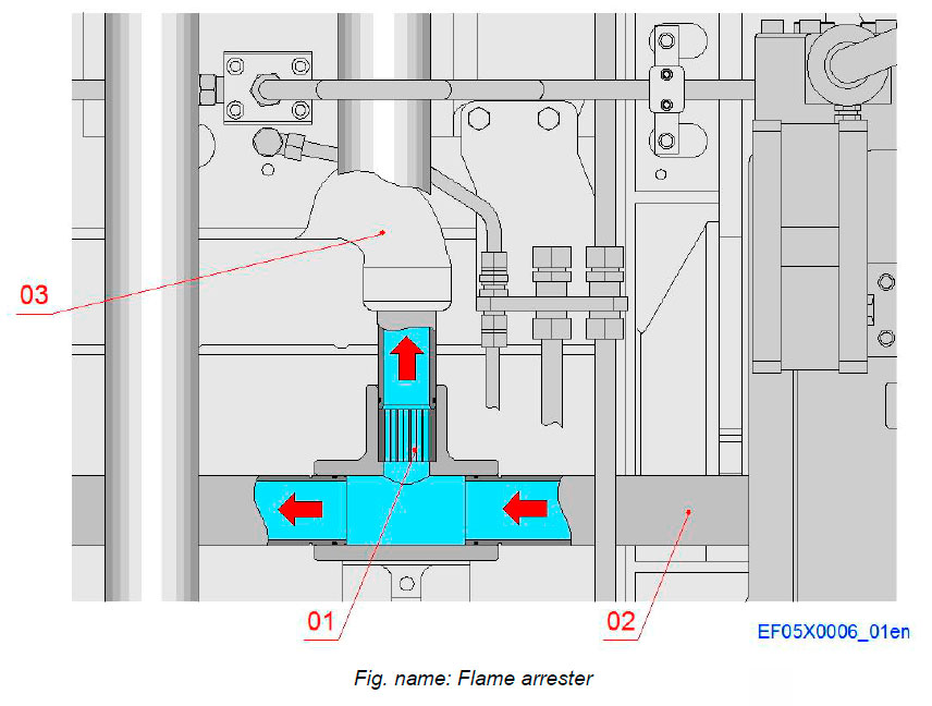
Each starting air pipe branch to the starting valve in cylinder head is provided with a flame arrester before the valve. The flame arrester prevents possible flame outburst from the combustion chamber if the cylinder in question fires before the starting sequence is over.
Components
- 01 Flame arrester
- 02 Starting air pipe
- 03 Cylinder head
Safety valve
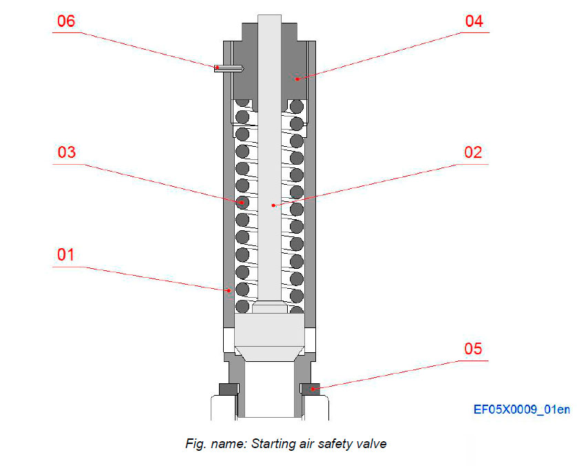
At the end of the starting air manifold (at the free end of the engine) there is a safety valve to relieve any sudden overpressure in the manifold.
Components
- 01 Housing
- 02 Spindle
- 03 Spring
- 04 Plug
- 05 Sealing ring
- 06 Spring pin
High pressure air filter
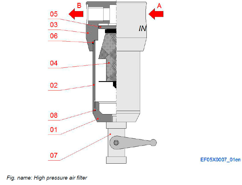
The flow-through-type high pressure air filter removes impurities from control air.
Components
- 01 Cover
- 02 Housing
- 03 Bottom
- 04 Filter
- 05 Socket
- 06 O-ring
- 07 Ball valve
- 08 O-ring
Connections
- A Air inlet
- B Air outlet
Water outlet valve
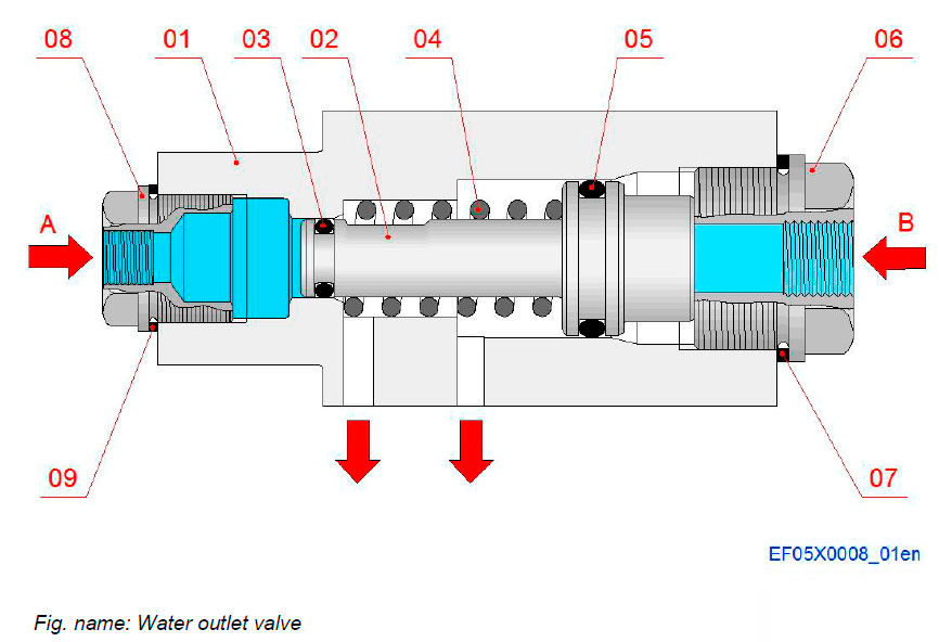
Water drained from the high pressure air filter is led to this water outlet valve, which is opened at the same time as the main starting valve.
Components
- 01 Housing
- 02 Piston
- 03 O-ring
- 04 Push spring
- 05 O-ring
- 06 Screw plug
- 07 Sealing ring
- 08 Screw plug
- 09 Sealing ring
Connections
- A Drain inlet from air filter
- B Control air inlet
Литература
www.wartsila.com

