Content
- Gas system arrangement - Internal
- Gas system on engine
- Gas delivery piping
- Gas admission valve assembly
- Gas admission valve
- Gas venting system
- Controlling equipment for venting
- Actuator for gas venting valve
- Ball valve for gas venting
- Inerting gas system for crank case
- Fuel system arrangement - Internal
- Fuel system on engine
- Covering system
- Hot-box side covers, upper part
- The Hot-box side covers, lower parts
- The Hot-box side covers, end covers
- The Hot-box side covers, between cylinder heads
Gas system arrangement - Internal
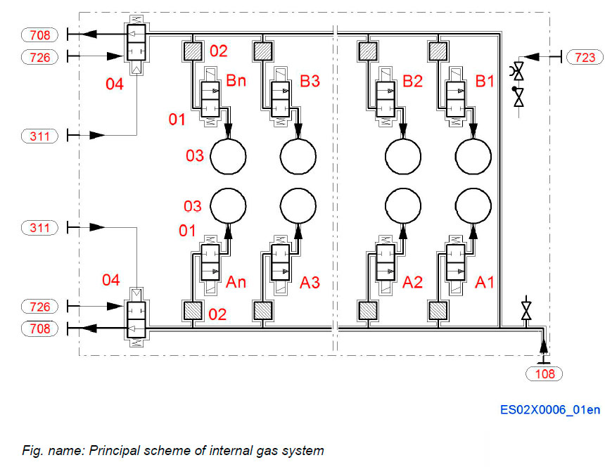
System components
- 01 Gas admission valve
- 02 Safety filter
- 03 Cylinder
- 04 Gas venting valve
Pipe connections
- 108 Gas inlet
- 311 Control air to gas venting valve
- 708 Gas system vent
- 723 Inert gas to crankcase
- 726 Air inlet to double wall system
Gas system on engine
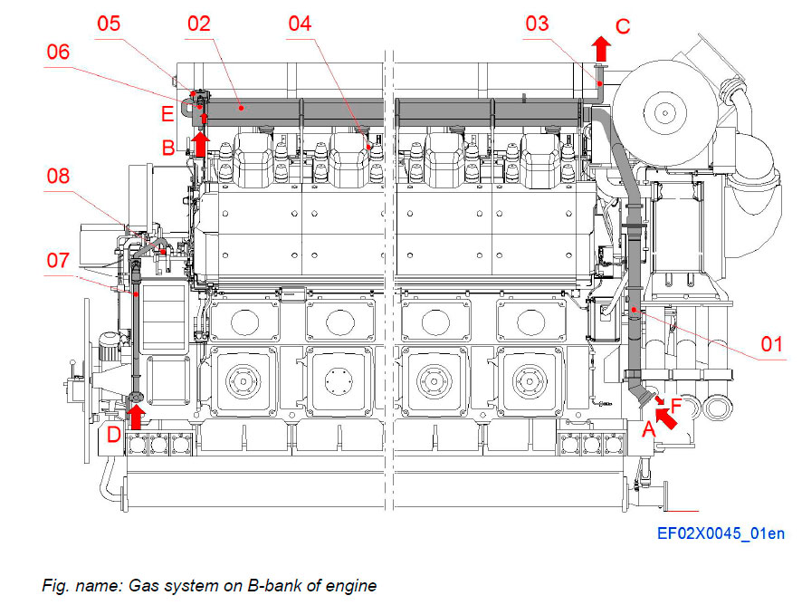
B-BANK
System components
- 01 Gas double wall inlet piping
- 02 Gas manifold
- 03 Gas venting piping
- 04 Gas admission valve
- 05 Actuator for venting valve
- 06 Venting valve
- 07 Nitrogen gas piping
- 08 Non-return valve
Pipe connections
- A 108 Gas inlet
- B 726 Air inlet to double wall system
- C 708 Gas system vent
- D 723 Inert gas to crankcase
- E 311 Control air to gas venting valve
- F Air outlet from double wall
A-BANK
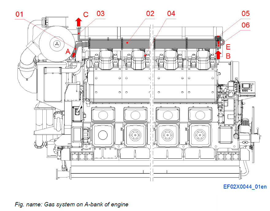
System components
- 01 Gas double wall inlet piping
- 02 Gas manifold
- 03 Gas venting piping
- 04 Gas admission valve
- 05 Actuator for venting valve
- 06 Venting valve
Pipe connections
- A 108 Gas inlet
- B 726 Air inlet to double wall system
- C 708 Gas system vent
- E 311 Control air to gas venting valve
Gas delivery piping
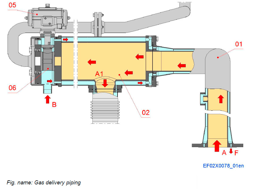
System components
- 01 Gas double wall inlet piping
- 02 Gas manifold
- 05 Actuator for venting valve
- 06 Venting valve
Pipe connections
- A Gas inlet
- B Air inlet to double wall system
- F Air outlet from double wall
Gas admission valve assembly
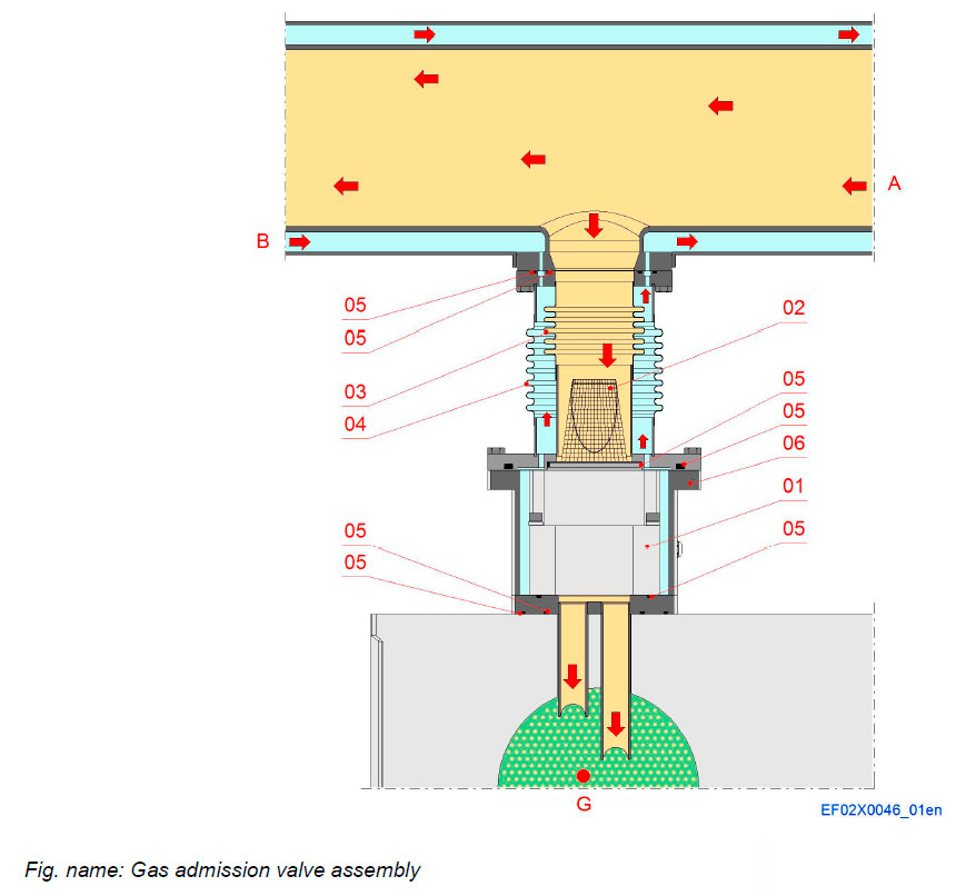
System components
- 01 Gas admission valve
- 02 Safety filter
- 03 Inner bellow
- 04 Outer bellow
- 05 O-ring
- 06 Protecting box
Pipe connections
- A Gas supply
- B Air flow
- G Charge air
Gas admission valve
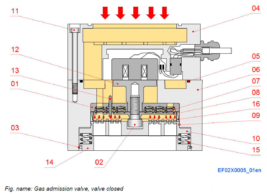
ACTUATION FORCE
All valve actuation forces are generated magnetically through an E-core solenoid device. Magnetic flux generated in the E-core solenoid assembly attracts a low carbon steel plate (the armature) that is attached to the valve mechanism. The E-core produces very high forces over short travels. The valve mechanism travels 0.50 mm from full closed to full open. The short travel along with the high forces result in fast and consistent opening and closing response.
Components
- 01 Upper plate
- 02 Screw
- 03 Retaining ring
- 04 Coil
- 05 O-ring
- 06 Valve housing
- 07 Spring
- 08 Moving plate
- 09 O-ring
- 10 Lower plate
- 11 Screw
- 12 Plate
- 13 Pin
- 14 Lower spring seat
- 15 Spring
- 16 Ring
Function
- A Coil de-energized, valve closed
VALVE
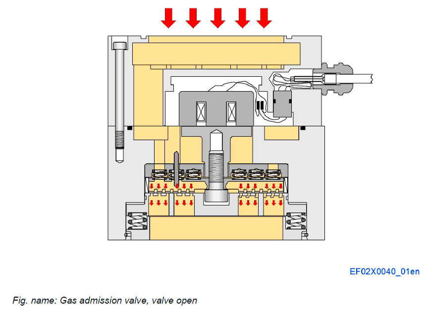
The valve is similar to an air (or gas) compressor valve. It is a face type poppet with multiple concentric grooves. The moving metering plate is spring loaded (and pressure loaded) against the lower stop & metering plate and is pulled off the lower stop & metering plate by the E-core solenoid assembly. When the plates are separated, gas flows from the grooves in the moving metering plate to the grooves in the lower stop & metering plate (View valve closed). When the moving metering plate and the lower stop & metering plate are in contact, gas cannot pass from the grooves in the moving metering plate to the grooves in the lower stop & metering plate (View valve open).
Function
- B Coil energized, valve open
Gas venting system
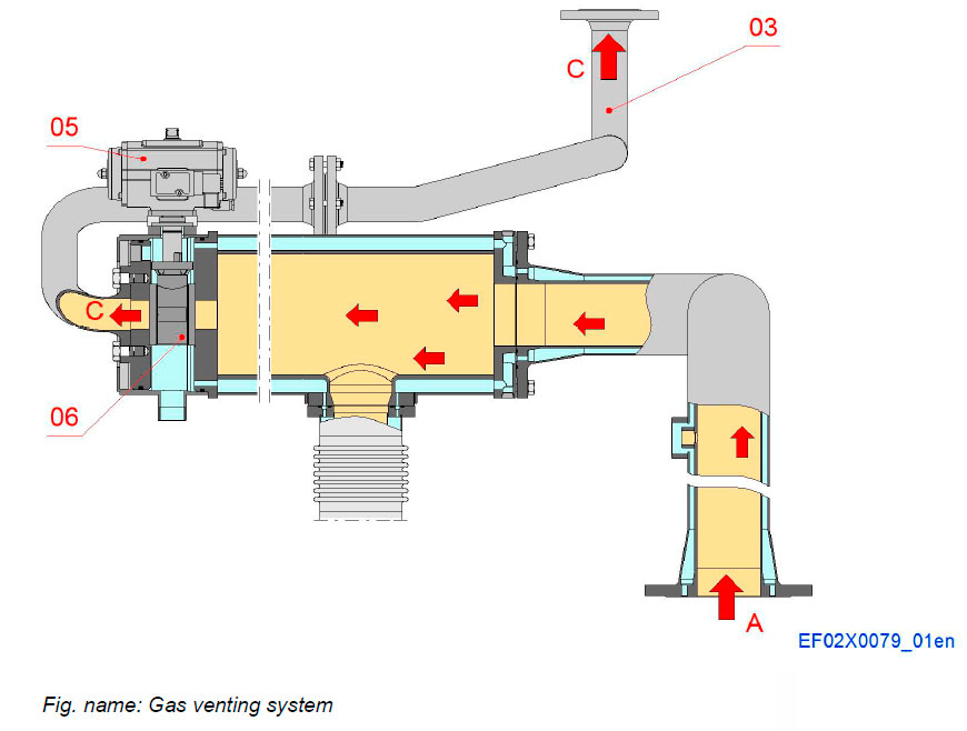
System components
- 03 Gas venting piping
- 05 Actuator for venting valve
- 06 Venting valve
Pipe connections
- A Gas inlet
- C Gas system vent
Controlling equipment for venting
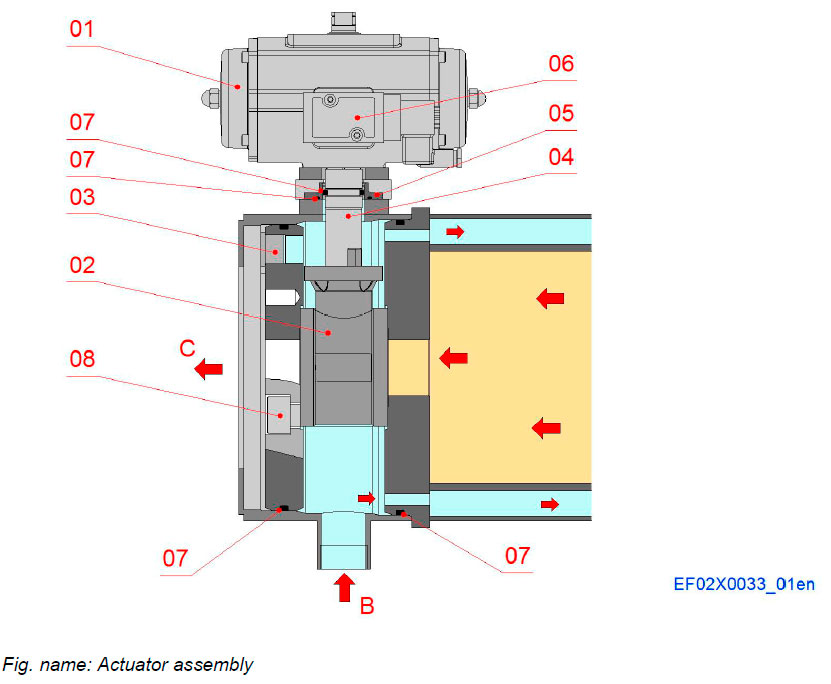
System components
- 01 Actuator
- 02 Vent valve
- 03 Plug for optional air suction
- 04 Shaft
- 05 Sealing flange
- 06 Solenoid valve
- 07 O-ring
- 08 Screw
Pipe connections
- B Air inlet to double wall system
- C Gas system vent
Actuator for gas venting valve
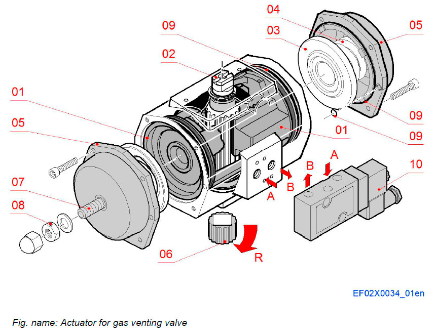
Components
- 01 Piston
- 02 Drive shaft
- 03 Spring holder
- 04 Spring
- 05 End cap
- 06 Insert
- 07 Limiter
- 08 Locking nut
- 09 O-ring
- 10 Control valve
Pipe connections
- A Air inlet
- B Air outlet
- R Spring open valve
Function
- R Spring open valve
Ball valve for gas venting
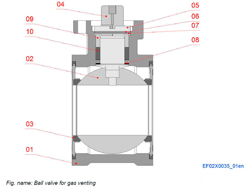
Components
- 01 Body
- 02 Ball
- 03 Sealing element
- 04 Operating stern
- 05 Stuffing box nut
- 06 Loading ring
- 07 Belleville washer
- 08 Female support ring
- 09 Stuffing box
Inerting gas system for crank case
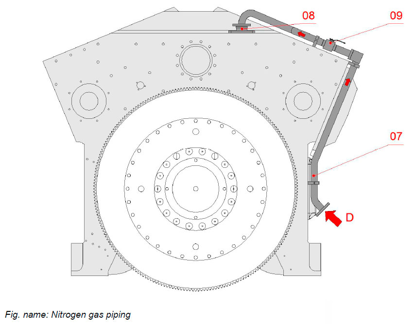
System components
- 07 Nitrogen gas piping
- 08 Non-return valve
- 09 Ball valve
Pipe connections
- D 723 Inert gas to crankcase
Fuel system arrangement - Internal
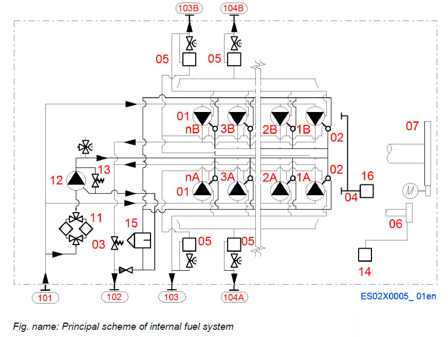
System components
- 01 Injection pump
- 02 Injection valve with pilot solenoid
- 03 Pressure control valve
- 04 Fuel rack
- 05 Fuel oil leakage collector
- 06 Camshaft
- 07 Flywheel
- 11 Pilot fuel filter
- 12 Pilot fuel pump
- 13 Pilot fuel safety valve
- 14 Mechanical over speed trip device
- 15 Water separator
- 16 Actuator
Pipe connections
- 101 Fuel inlet
- 102 Fuel outlet
- 103 Clean fuel leakage outlet
- 104 Dirty fuel leakage outlet
Fuel system on engine
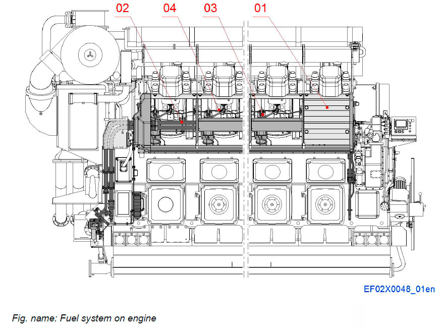
The arrangement on the engine consist of covering system, low pressure system, main injection and pilot injection systems with control devices and fuel condition monitoring systems.
System components
- 01 Covering system
- 02 Low pressure system
- 03 Main injection system
- 04 Pilot injection system
Covering system
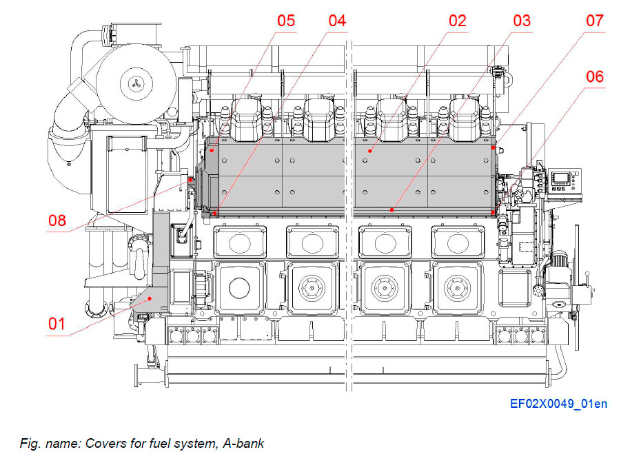
A-BANK
The hot-box covering system can be divided into four categories, cover for fuel piping, end covers, side covers and covers between the cylinder heads.
System components
- 01 Covers for fuel piping
- 02 Side covers, upper part
- 03 Side covers, lower part
- 04 End cover FE, lower part
- 05 End cover FE, upper part
- 06 End cover DE, lower part
- 07 End cover DE, upper part
- 08 Covers for fuel piping from
A-bank to B-bank
B-BANK
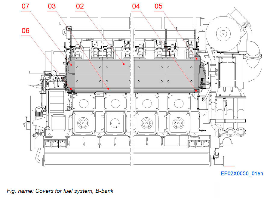
The hot-box covering system can be divided into four categories, cover for fuel piping, end covers, side covers and covers between the cylinder heads.
System components
- 02 Side covers, upper part
- 03 Side covers, lower part
- 04 End cover FE, lower part
- 05 End cover FE, upper part
- 06 End cover DE, lower part
- 07 End cover DE, upper part
COVERS FROM A-BANK TO B-BANK
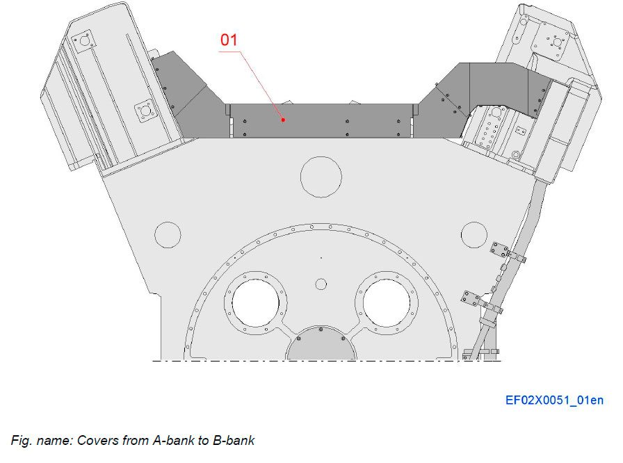
The Hot-box covers are designed to form an isolated area. The splash covers are giving even higher protection for the same area by preventing direct pressurized fuel injection to hot surfaces.
System components
- 01 Covers for fuel piping from
A-bank to B-bank
Hot-box side covers, upper part
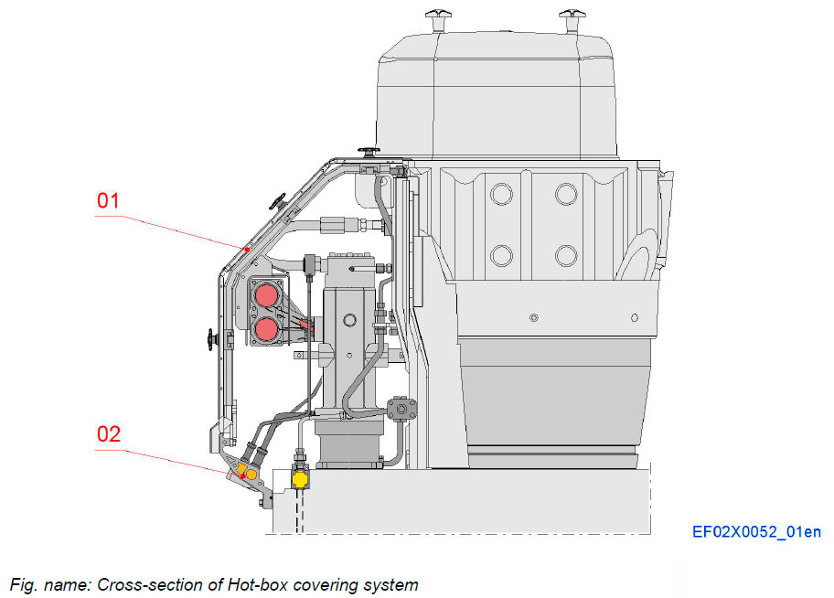
Basically the Hot-box side covers are built on the frame, which at the lower end are retained by means of screws onto the lower side cover profile. The lower side cower in turn is attached onto the side surface of the engine block. At the upper end, the system is attached to the cylinder head. Side cover consist of three covers as lower cover, middle cover and upper cover.
Every side cover is secured to the frame with latch mechanism.
System components
- 01 Hot-box side covers, upper part
- 02 Hot-box side covers, lower part
The Hot-box side covers, lower parts
A-BANK
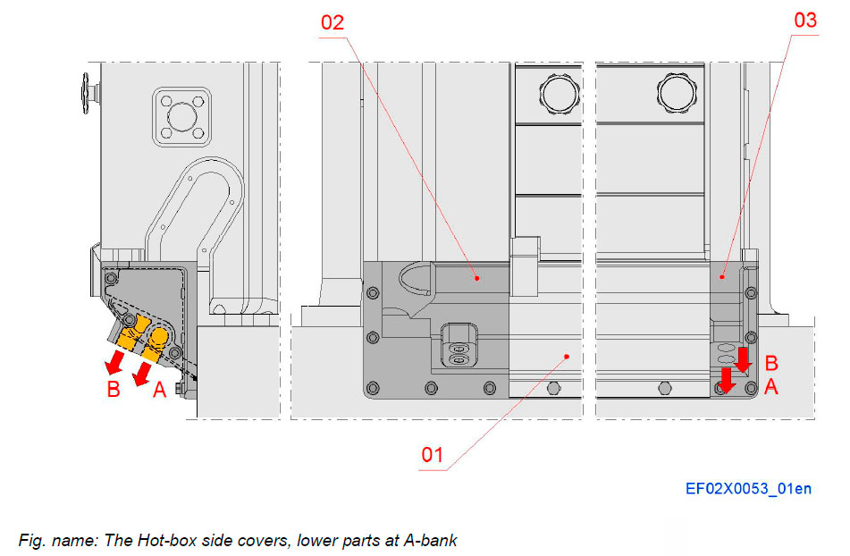
The lower side covers are attached directly to the cylinder block, and also provide passages for leak fuel.
System components
- 01 Side cover lower part
- 02 End cover lower part, FE
- 03 End cover lower part; DE
Connections
- A Main fuel leakage, from injection pump
- B Main fuel leakage, from high pressure pipe
B-BANK
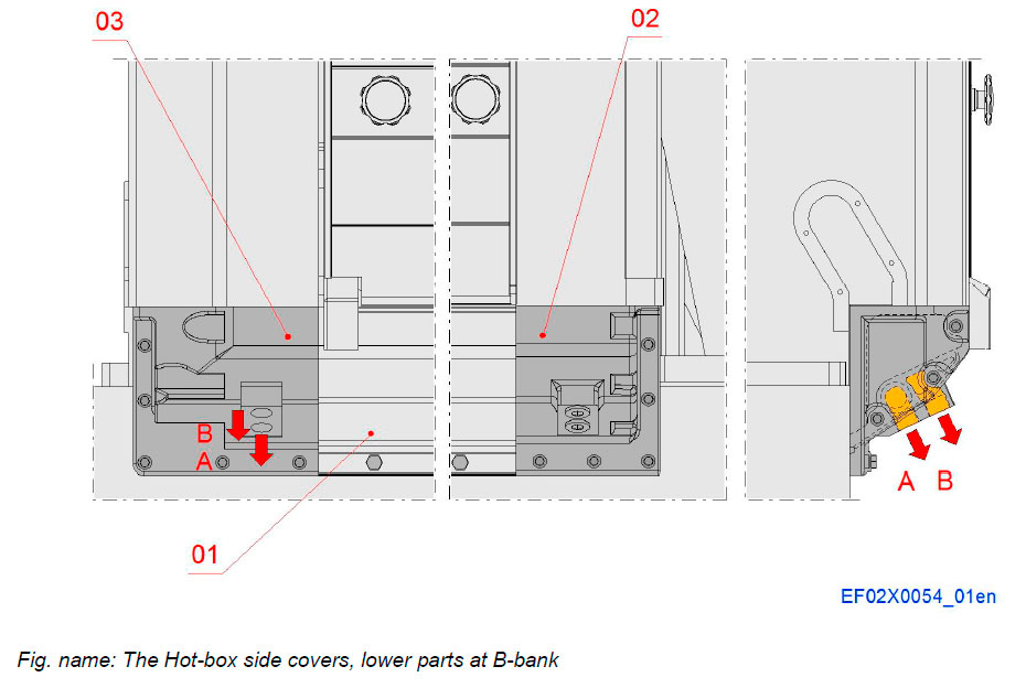
The lower side covers are attached directly to the cylinder block, and also provide passages for leak fuel.
System components
- 01 Side cover lower part
- 02 End cover lower part, FE
- 03 End cover lower part; DE
Connections
- A Main fuel leakage, from injection pump
- B Main fuel leakage, from high pressure pipe
The Hot-box side covers, end covers
A-BANK
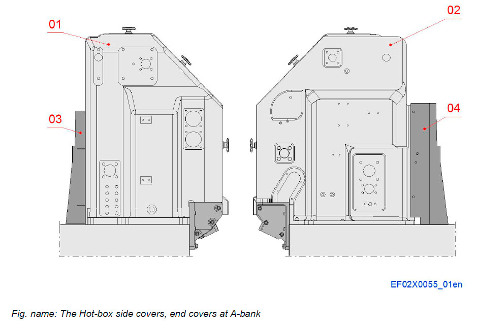
The Hot-box covers are designed to form an isolated area. The splash covers are giving even higher protection for the same area by preventing direct pressurized fuel injection to hot surfaces.
System components
- 01 End cover, FE
- 02 End cover, DE
- 03 Splash cover
- 04 Splash cover
B-BANK
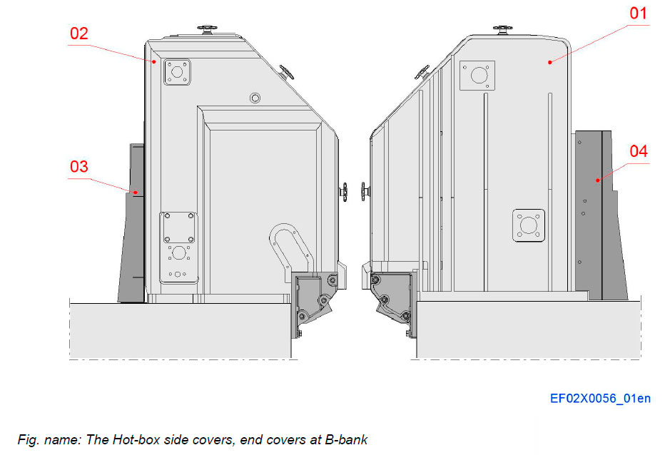
The Hot-box covers are designed to form an isolated area. The splash covers are giving even higher protection for the same area by preventing direct pressurized fuel injection to hot surfaces.
System components
- 01 End cover, FE
- 02 End cover, DE
- 03 Splash cover
- 04 Splash cover
The Hot-box side covers, between cylinder heads
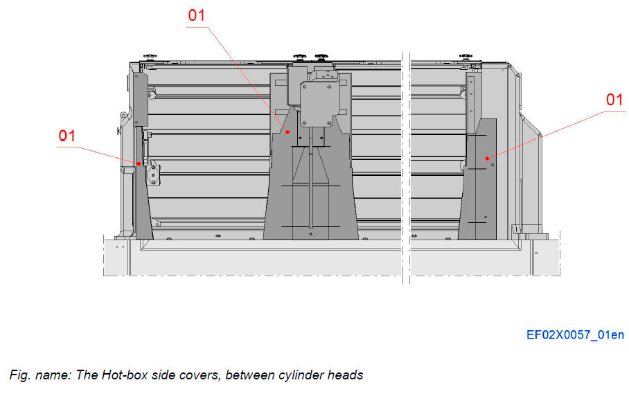
The Hot-box covers are designed to form an isolated area. The splash covers are giving even higher protection for the same area by preventing direct pressurized fuel injection to hot surfaces.
System components
- 01 Splash cover
Литература
www.wartsila.com

