Engine block
The engine block is made of cast iron in one piece. The block has been given a stiff and durable design to absorb internal forces. It works as a frame, where the most of the other components are mounted on.
The main bearing caps are fixed by hydraulically tightened screws. A combined flywheel/thrust bearing is located at the driving end of the engine.
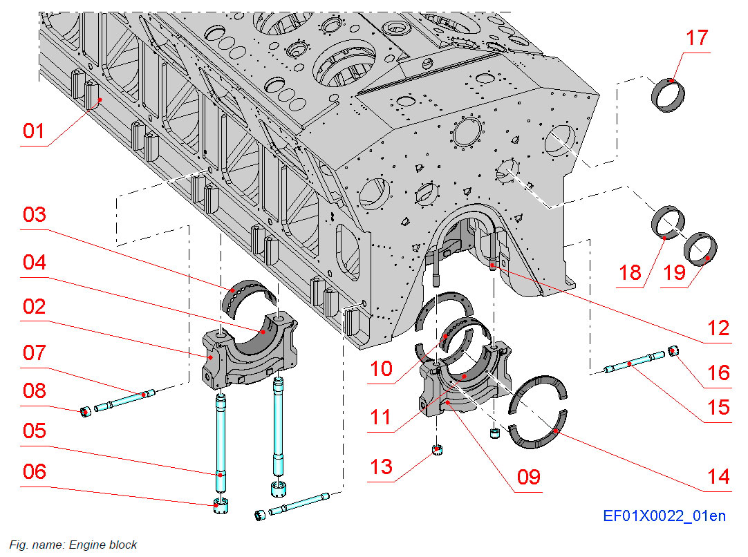
COMPONENTS
- 01 Engine block
- 02 Main bearing cap
- 03 Main bearing shell, upper
- 04 Main bearing shell, lower
- 05 Main bearing cap screw
- 06 Main bearing cap nut
- 07 Lateral tie screw
- 08 Lateral tie screw nut
- 09 Thrust bearing cap
- 10 Thrust bearing shell, upper
- 11 Thrust bearing shell, lower
- 12 Thrust bearing cap screw
- 13 Thrust bearing cap nut
- 14 Thrust bearing rail
- 15 Lateral tie screw
- 16 Lateral tie screw nut
- 17 Camshaft bearing bush
- 18 Intermediate shaft bearing bush
- 19 Intermediate shaft bearing bush, driving end
MAIN AND THRUST BEARINGS
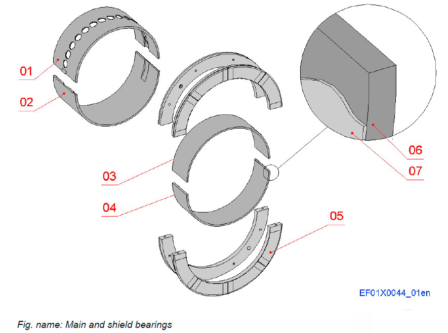
The main and thrust bearings are bi-metal aluminium bearings with steel back and AlSn+ lining.
The main bearing shells offer a good sliding surface for the crankshaft journals in the main bearing caps.
COMPONENTS
- 01 Main bearing shell, upper
- 02 Main bearing shell, lower
- 03 Thrust bearing shell, upper
- 04 Thrust bearing shell, lower
- 05 Thrust bearing rail
LAYERS
- 06 Steel shell
- 07 Lining: AlSn+
CAMSHAFT AND INTERMEDIATE SHAFT BEARINGS
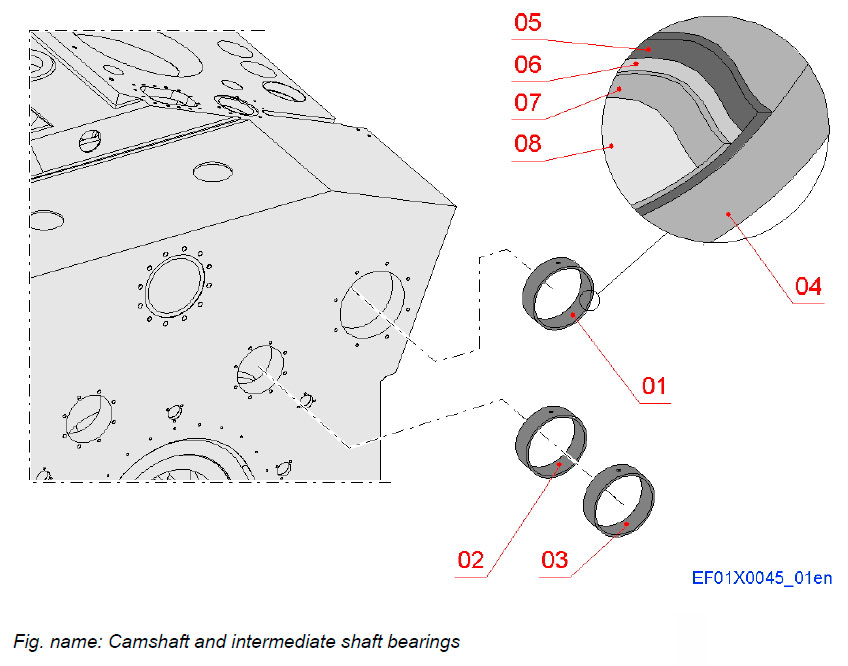
The camshaft and intermediate shaft bearings are of tri-metal type with steel back and lead bronze lining.
COMPONENTS
- 01 Camshaft bearing bush
- 02 Intermediate shaft bearing bush
- 03 Intermediate shaft bearing bush, driving end
LAYERS
- 04 Steel shell
- 05 Lead bronze lining
- 06 Nickel dam
- 07 Tin-antimony overlay
- 08 Tin flash
Oil sump
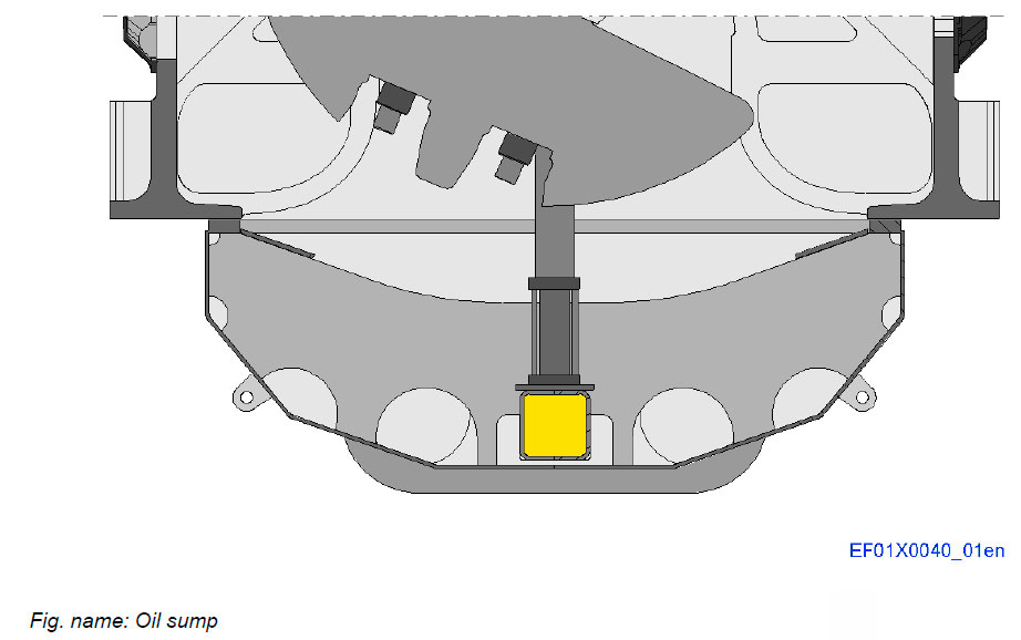
The oil sump is of welded design and it increases the strength and rigidity of the engine block.
The oil sump is of dry type, i.e. a separate system oil tank is needed.
After circulation the lubricating oil is drained to the oil sump.
Covers
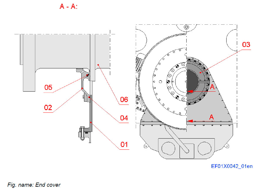
END COVER
The crankshaft through hole at the driving end of the engine is covered with a three-piece cover and sealed with a V-ring.
COMPONENTS
- 01 End cover
- 02 End cover, lower half
- 03 End cover, upper half
- 04 O-ring
- 05 V-ring
- 06 Crankshaft
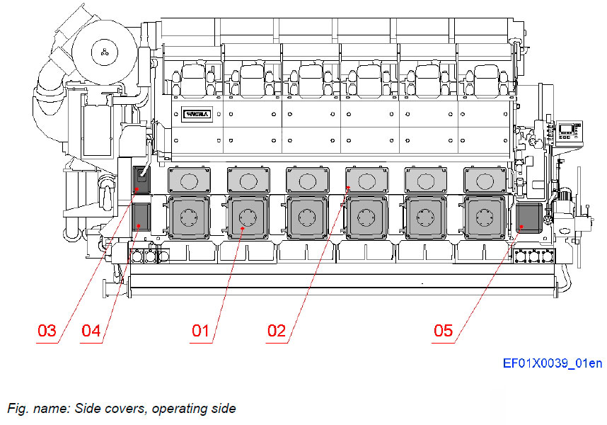
SIDE COVERS, OPERATING SIDE
The crankcase covers and camshaft covers are made of cast light-weight metal. They are sealed against the engine block by means of rubber seals.
The crankcase covers and camshaft covers are tightened against the crankcase with screws.
Some of the crankcase covers are provided with hinges.
COMPONENTS
- 01 Crankcase cover
- 02 Camshaft cover
- 03 Cover
- 04 Cover for drive gear
- 05 Cover for split gear
SIDE COVERS, REAR SIDE
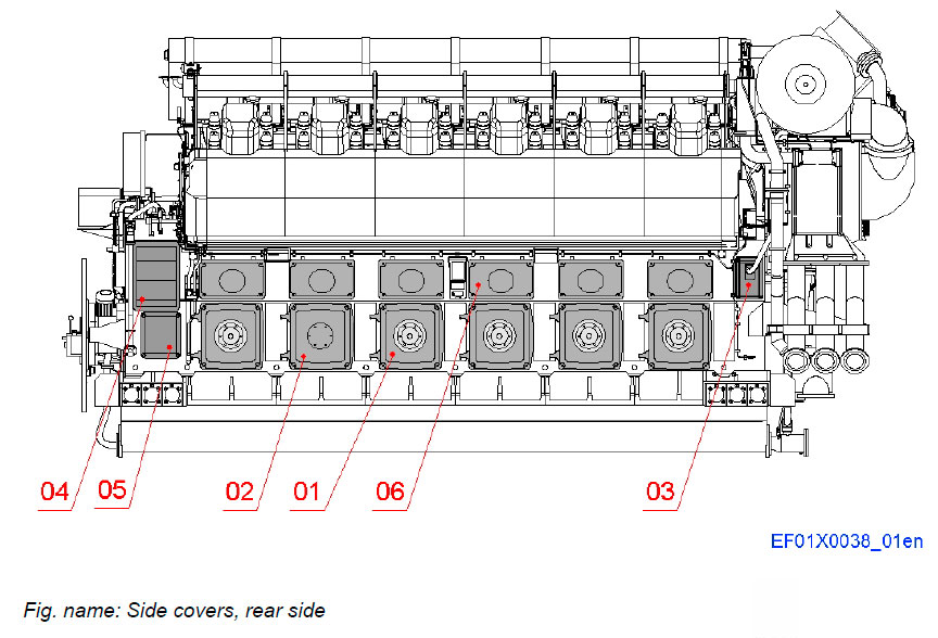
Some of the crankcase covers on the rear side of the engine are equipped with a safety valve which relieve the overpressure in case of a crankcase explosion. The number of relief valves depends on the crankcase volume.
COMPONENTS
- 01 Crankcase cover with relief valve
- 02 Crankcase cover without relief valve
- 03 Cover
- 04 Cover for intermediate gear
- 05 Cover for split gear
- 06 Camshaft cover
CRANKCASE COVER WITH RELIEF VALVE
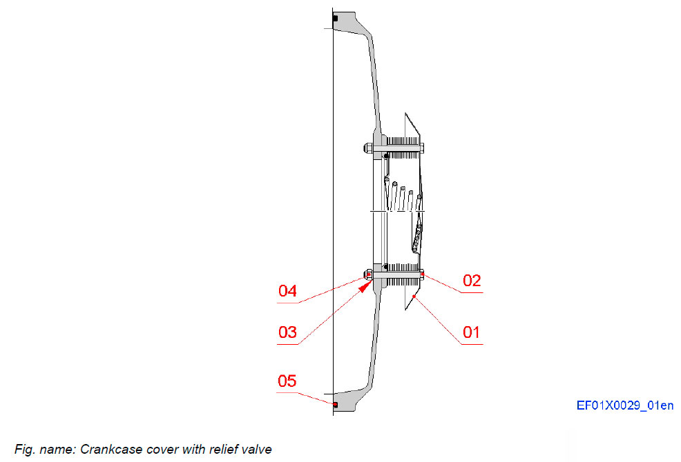
COMPONENTS
- 01 Relief valve
- 02 Screw
- 03 Sealing ring
- 04 Nut
- 05 O-ring
Crankshaft
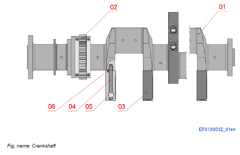
The reciprocating motion of the pistons and the connecting rods are converted into a rotating motion of the crankshaft. The power of the engine can then be taken out to the application through a powerful connection at the crankshaft.
COMPONENTS
- 01 Crankshaft
- 02 Split gear wheel
- 03 Counterweight
- 04 Screw for counterweight
- 05 Round nut
- 06 Dowel pin
CRANKSHAFT EQUIPMENT
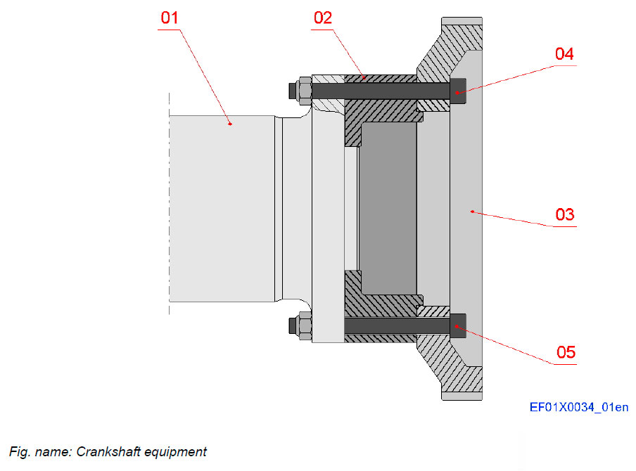
The crankshaft is equipped with a drive gear to drive water pumps and the oil pump.
COMPONENTS
- 01 Crankshaft
- 02 Distance ring
- 03 Drive gear
- 04 Fitting screw
- 05 Screw
Connecting rod
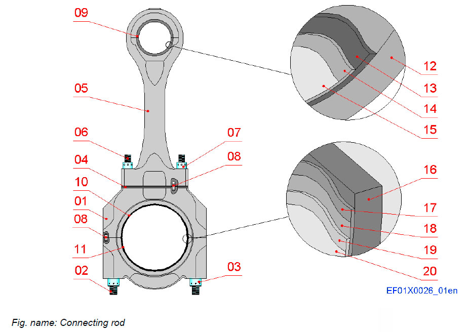
The connecting rod converts the reciprocating motion of the piston to a rotating motion of the crankshaft.
COMPONENTS
- 01 Connecting rod, lower part
- 02 Screw
- 03 Round nut
- 04 Shim
- 05 Connecting rod, upper part
- 06 Screw
- 07 Round nut
- 08 Dowel pin
- 09 Bearing bush
- 10 Big end bearing shell, upper
- 11 Big end bearing shell, lower
CONNECTING ROD BEARINGS
LAYERS
- 12 Steel shell
- 13 Lead bronze lining
- 14 Lead bronze overlay
- 15 Lead tin flash
- 16 Steel shell
- 17 Lead bronze lining
- 18 Nickel dam
- 19 Tin-antimony overlay
- 20 Tin flash
Piston
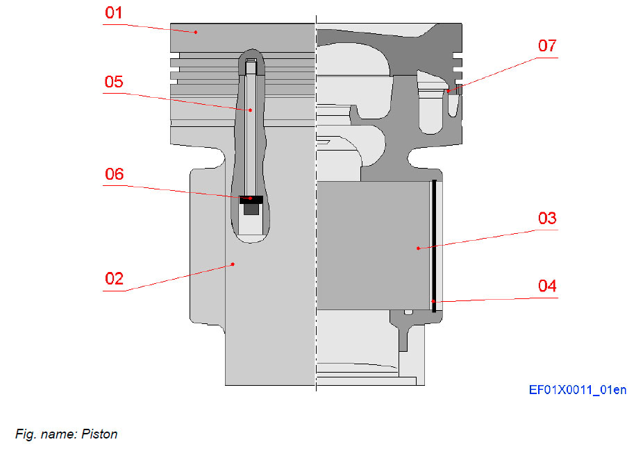
The piston conveys the energy coming from the combustion of the fuel to the connecting rod.
Due to the explosion in the combustion chamber the piston is pushed down and the motion is transferred to the crankshaft by the connecting rod.
COMPONENTS
- 01 Piston crown
- 02 Piston skirt
- 03 Piston pin
- 04 Retaining ring
- 05 Screw
- 06 Distance sleeve
- 07 O-ring
PISTON RINGS
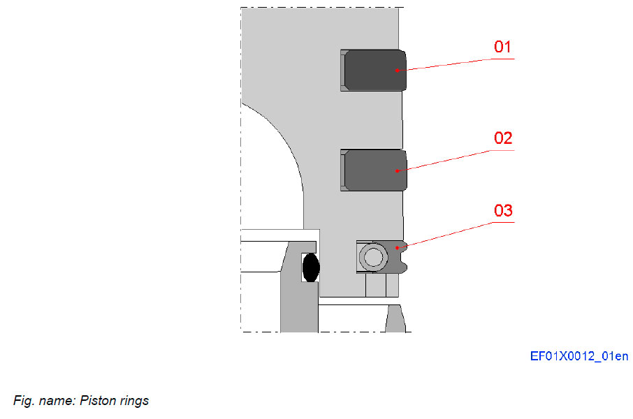
Piston rings maintain combustion pressure, prevent lubricating oil from getting into the combustion chamber and aid in the control of thermal changes in the engine.
COMPONENTS
- 01 Compression ring I
- 02 Compression ring II
- 03 Oil scraper ring
Cylinder liner
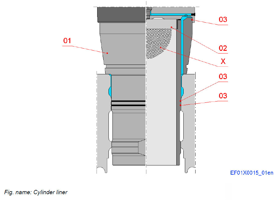
The cylinder liner forms the combustion space where the piston moves back and forth.
The antipolishing ring at the top of the cylinder liner removes deposits from the piston top on every stroke.
The top of the liner is bore cooled.
COMPONENTS
- 01 Cylinder liner
- 02 Antipolishing ring
- 03 O-ring
- X Honing marks
Intermediate gearing
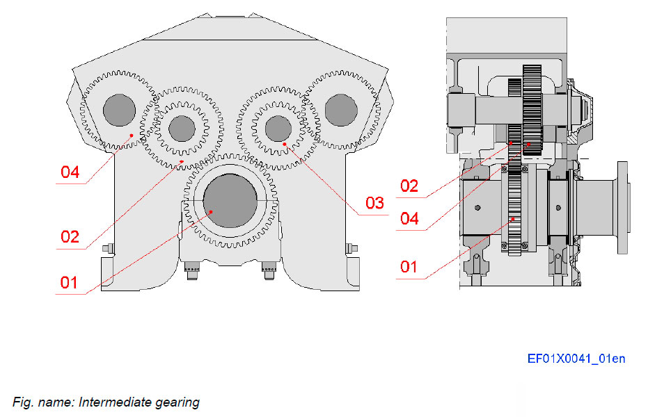
The rotating movement of the crankshaft is transferred to the camshaft via intermediate gearing.
COMPONENTS
- 01 Crankshaft gear
- 02 Bigger intermediate gear
- 03 Smaller intermediate gear
- 04 Camshaft gear
Turning device
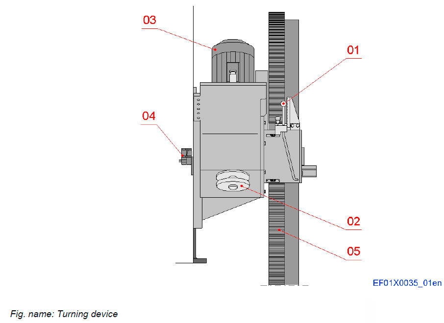
Turning of the crankshaft is performed by means of an electrically driven turning device built on the engine.
The turning device consists of an electric motor which drives the turning gear through a gear drive and a worm gear.
COMPONENTS
- 01 Lever
- 02 Hand wheel
- 03 Electric motor
- 04 Start blocking valve
- 05 Flywheel
Camshaft
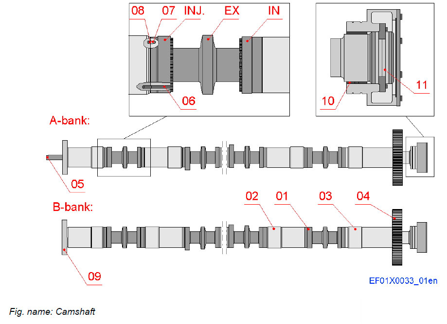
The camshaft is made up of one-cylinder sections with integrated cams. The bearing journals are separate pieces.
The camshaft operates the inlet and exhaust valve mechanisms and fuel injection pump.
COMPONENTS
- 01 Camshaft piece
- 02 Bearing piece
- 03 Extension shaft
- 04 Camshaft gear wheel
- 05 Starting cam
- 06 Screw
- 07 Guiding pin
- 08 Snap ring
- 09 Vibration damper
- 10 Bearing bush
- 11 Thrust bearing
CAMSHAFT BEARING, DRIVING END
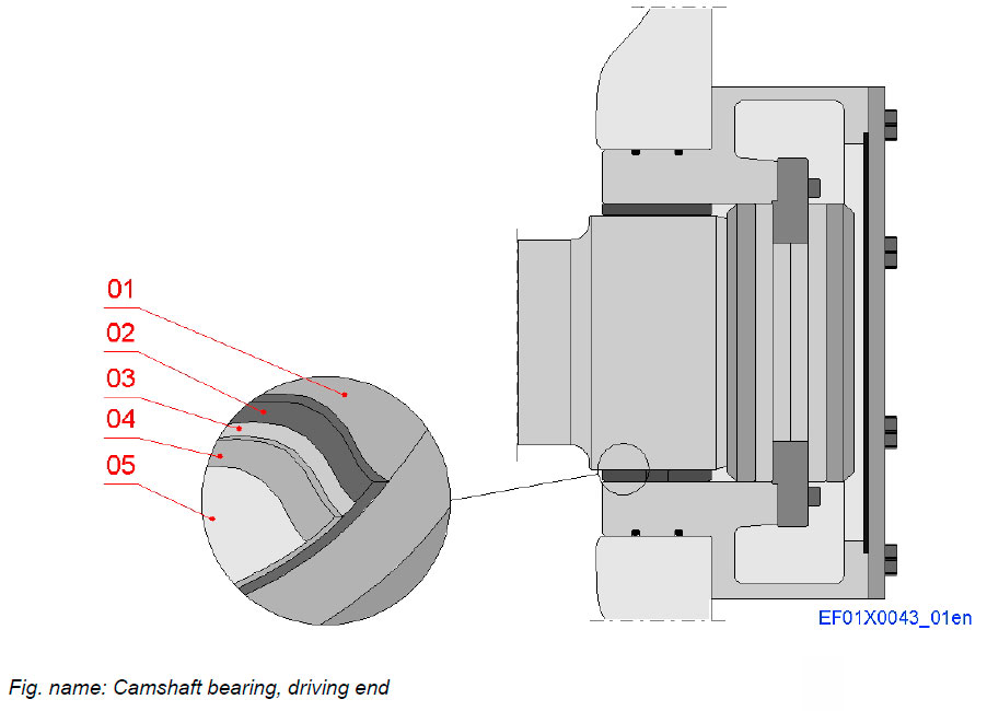
The camshaft driving end bearing is of tri-metal type with steel back and lead bronze lining.
LAYERS
- 01 Steel shell
- 02 Lead bronze
- 03 Nickel dam
- 04 Tin-antimony overlay
- 05 Tin flash
CAMSHAFT WITH VIBRATION DAMPER
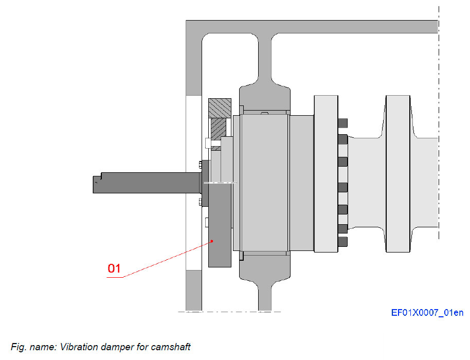
The camshaft can be equipped with a vibration damper, which is fastened to the camshaft with screws.
The damper is needed on the camshaft to minimize torsional vibrations and keep material stresses within permissible limits. It ensures a smoother running of the engine by reducing oscillations in the camshaft.
COMPONENTS
- 01 Vibration damper for camshaft
Valve mechanism
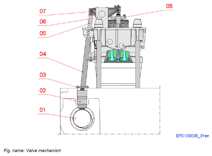
Valve tappets follow the cam profile of a rotating camshaft and transfer the movement through push rods to the rocker arms.
The rocker arms operate inlet and exhaust valves through a yoke.
COMPONENTS
- 01 Camshaft
- 02 Valve tappet
- 03 Cover
- 04 Protecting pipe
- 05 Push rod
- 06 Rocker arm bracket
- 07 Rocker arm
- 08 Yoke
Cylinder head
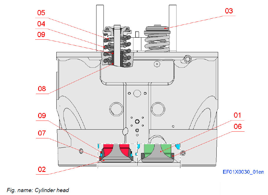
The cylinder head is a cover for the combustion space where the valves for gas exchange are located. The cylinder head is made of nodular cast iron and it is fastened on the engine with four cylinder head screws.
Inlet and exhaust outlets are on the same side, allowing for compact design of exhaust manifold and charge air receiver arrangement and easy maintenance. Two inlet valves and two exhaust valves are all provided with valve rotators.
COMPONENTS
- 01 Inlet valve
- 02 Exhaust valve
- 03 Valve rotator
- 04 Valve spring, outer
- 05 Valve spring, inner
- 06 Inlet seat ring
- 07 Exhaust seat ring
- 08 Valve guide
- 09 O-ring
EXHAUST SEAT COOLING
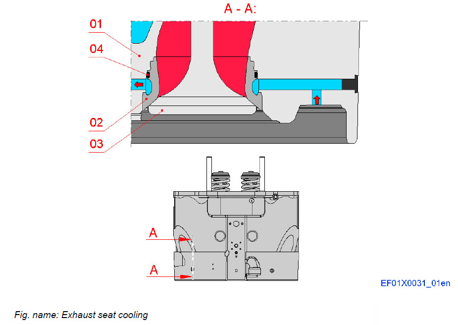
Cooling of the valve and the seat ring is optimized by placing the cooling channel very close to the seat contact surface.
COMPONENTS
- 01 Cylinder head
- 02 Exhaust seat ring
- 03 Exhaust valve
- 04 O-ring
CYLINDER HEAD GASKET
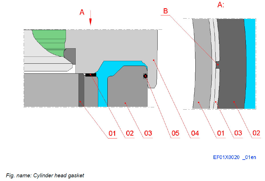
The cylinder head gasket separates the combustion space and the water space between the cylinder head and cylinder liner.
The radial guiding of the gasket is taken care of by the guiding lugs (B).
COMPONENTS
- 01 Antipolishing ring
- 02 Gasket
- 03 Cylinder liner
- 04 Cylinder head
- 05 O-ring
Литература
www.wartsila.com

