Content
- Layout
- Components required in a DF installation
- DF control network
- Unit Control Panel
- Wärtsilä Operator’s Interface System
- Gas Valve Unit
- Exhaust ventilation fan
- Motor Control Centre
- Synchronising panel (option)
- DF control and synchronizing
- Start of DF engine in gas mode
- Engine operating modes
- Fuel transfer window
- Gas feed system 50DF
- Stop of DF engine
- Simple Hard Wired Interface
- UCP instruments
- Protection relays
- Local Control Unit
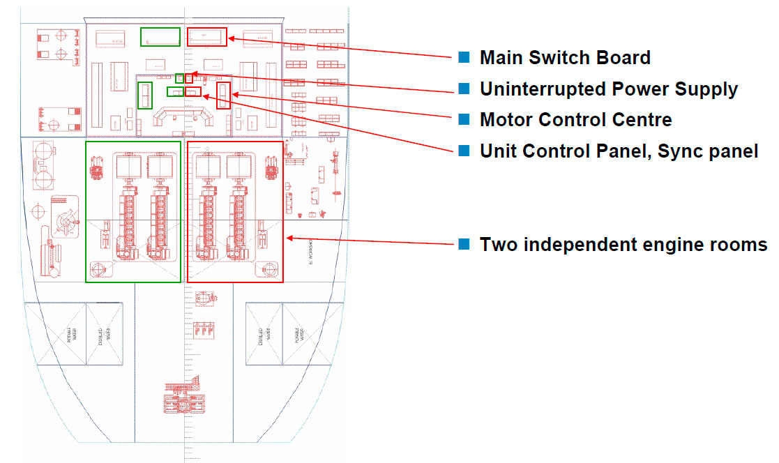
Layout
Components required in a DF installation
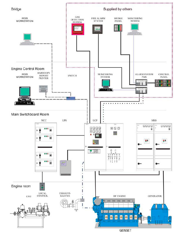
DF ENGINE + GENERATOR
- Auxiliaries:
- Exhaust gas ventilation fan
- Gas Valve Unit
- Cooling Water Pre-heater
- Water thermostatic valves
- Etc...
- MV Main Switch Board
- Unit Control Panel
- Synchronising panel
- Motor Control Centre (MCC)
- Uninterrupted Power Supply (UPS)
- Wärtsilä Operator’s Interface System, workstations (WOIS)
- Gas detection system
- Emergency Shut Down system (ESD)
DF control network
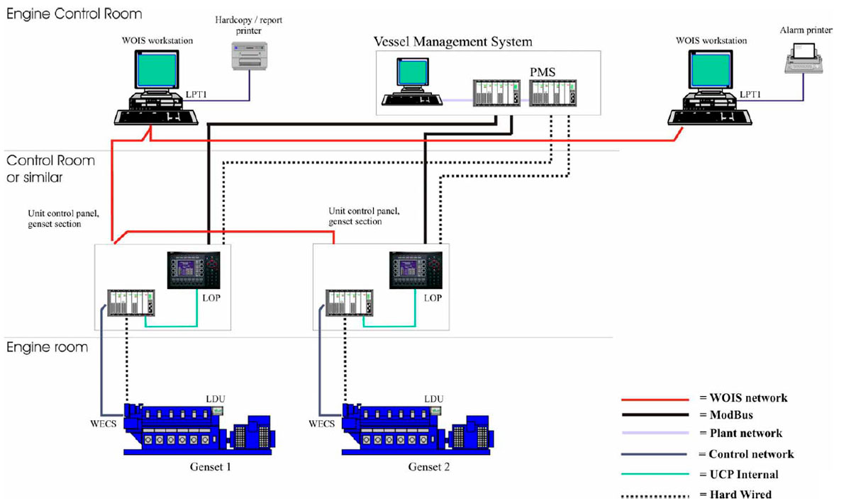
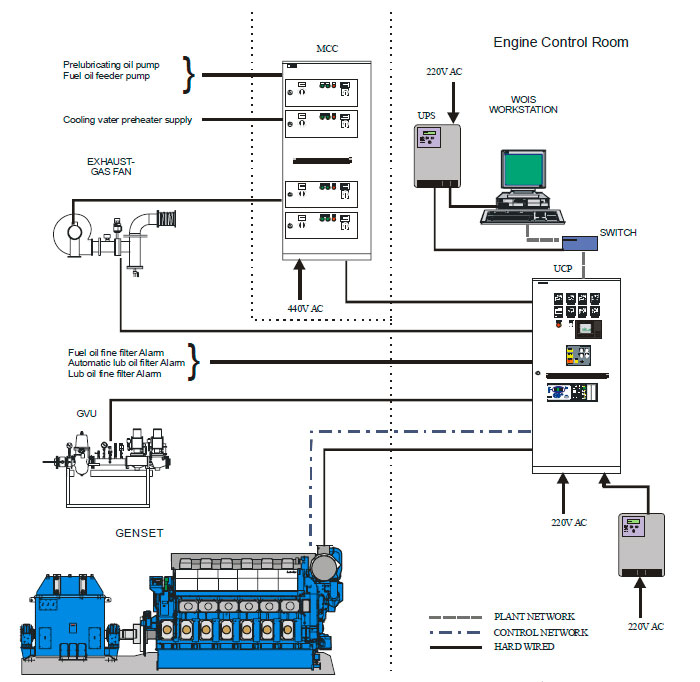
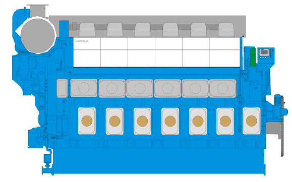
ENGINE MOUNTED:
WECS (8000)
- Engine monitoring
- Engine safety
- Electronic Fuel Injection
- Pilot injection
- Gas valve control
- Speed control
- Gas mode
- Diesel mode
- Fuel transfer control
- Slow turning
- Generator sensors connected to WECS* (* = if generator supplied by Wärtsilä)
Local indication
Interface to UCP
Unit Control Panel
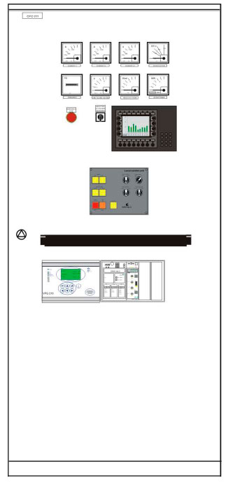
ENGINE WISE FLOOR STANDING CABINET (IP32)
Includes:
- Local control unit
- Local display unit (WOIS or mini-WOIS)
- PLC + I/O modules
- Generator instruments
- Redundant power converters (control voltage for UCP, MCC and WECS)
- HT- and LT- water thermostatic valve controller
- Redundant power supply
- Barriers for GVU
- Torsional vibration monitor
- Emergency stop pushbutton
- Power monitoring unit (PMU) (option)
- Isochronous load sharing unit (option)
- Generator protection relays (option)
- AVR (option)
- Interface to synchronising panel (option)
Control and monitors:
- Fuel supply to DF engine
- Fuel modes of the DF engine
- Data communication
- GVU
- Exhaust gas fan
- Prelubricating oil pump
- Engine pre heater
- LT-water thermostatic valve
- HT-water thermostatic valve
- Filters
Wärtsilä Operator’s Interface System
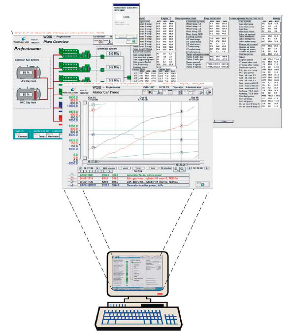
WOIS:
- Graphical process pages
- Long time trends, with high sampling frequency
- Start sequence / start blocking
- Shutdown reason
- Gas / pilot trip reason
- Alarm lists
- Event lists
- Instant reports
- Send hard copy of pages to printer
- Print alarms / events
WISE:
- Daily max, min, average values, calculated when engine load is above set point
- Daily max, min, average values calculated on common values
- Long time trend of above calculated values
- Electronic log book. Engine start and stop automatically logged
- Production report on energy produced, fuel consumption, etc (depending on values measured)
- Remote help, if WISE is connected by e-mail to Wärtsilä
Gas Valve Unit
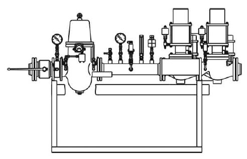
DESIGNED FOR GAS ZONE 1
- Engine specific
- Controlled by UCP
- Power supply from UCP
- Ex barriers located in UCP (Option, at GVU)
- EEx solenoids
- EEx ia temp. & pres. Transmitters
Leakage test done before every gas supply Gas pressure regulating valve (if not engine mounted or loose)
Exhaust ventilation fan
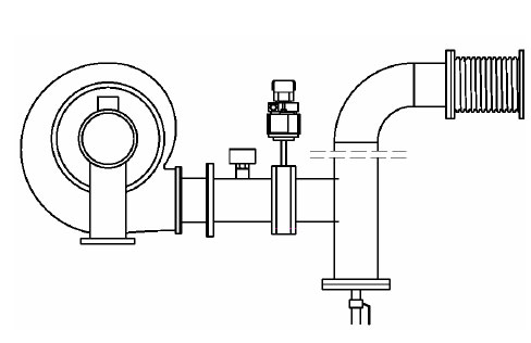
- Controlled /monitored by UCP
- Fan motor supplied from MCC
- Flow switch
- Electro-pneumatically actuated valve
The exhaust gas ventilation is always requested by DF-engine control system after DF-engine has stopped, due to whatever reason, if gas fuel has been utilised in the engine within two minutes prior to stop.
Motor Control Centre
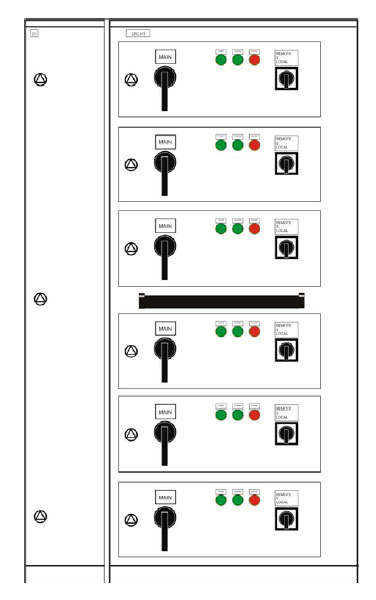
Wall mounted or floor standing cabinet normally IP44
Engine or engine compartment wise
Feeder for:
- Engine CW Pre heater
Starter for:
- Pre lubricating oil pump
- Fuel oil feeder pump
- Exhaust gas ventilation fan
- Pilot fuel pump (if not engine driven)
Monitored by UCP
Synchronising panel (option)
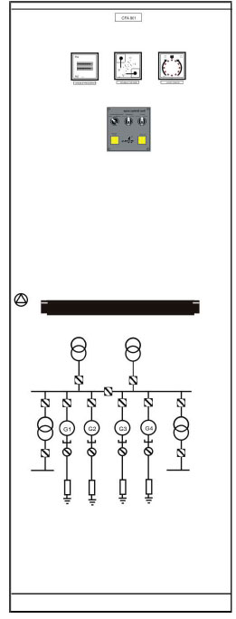
Floor standing cabinet (IP32)
- Synchronising instruments
- Auto synchroniser
- Sync check relay
- Manual synchronising
- Main MIMIC
- Tie breaker synchronising
DF control and synchronizing
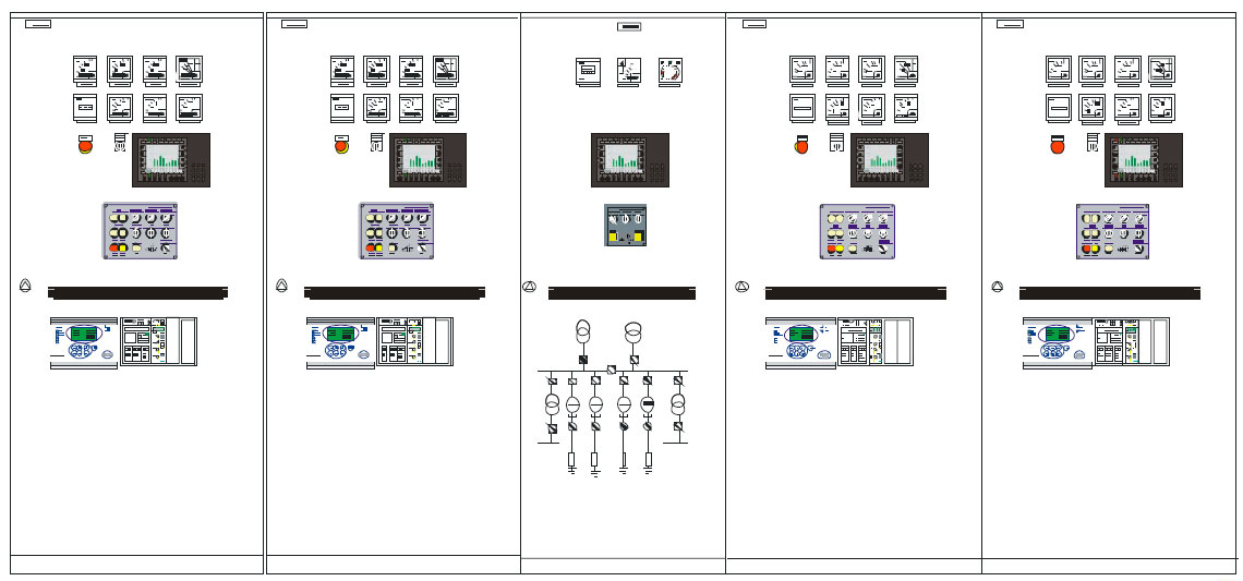
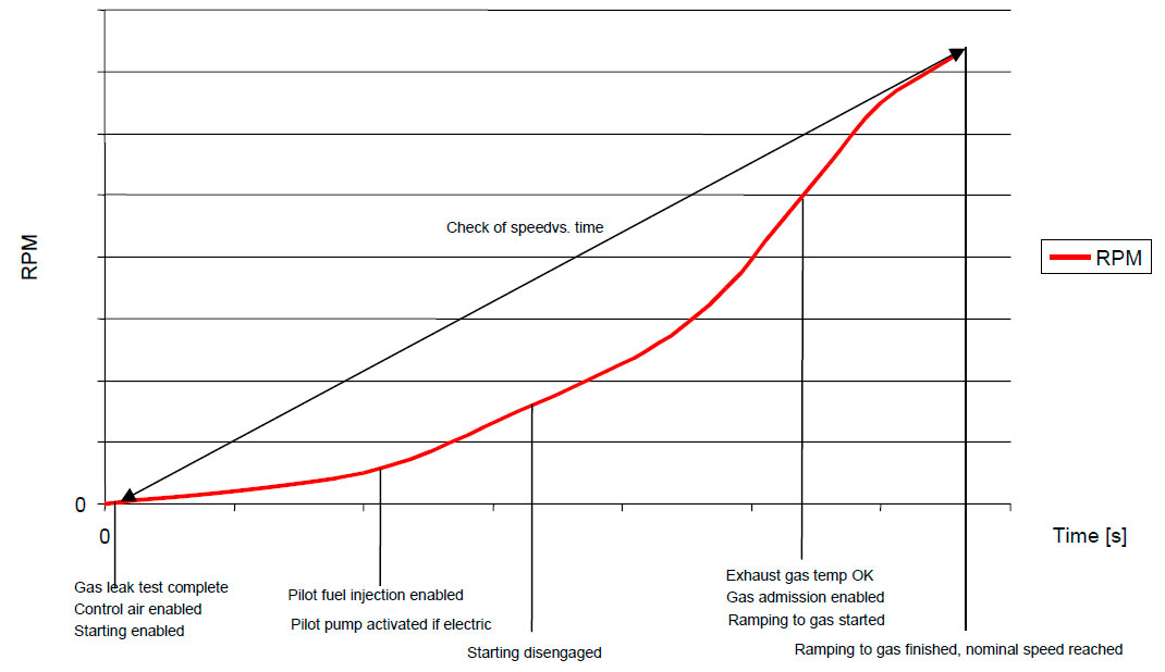
Start of DF engine in gas mode
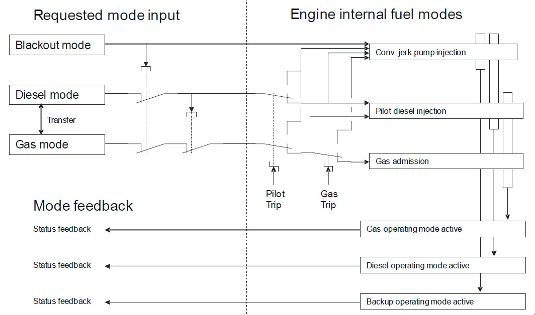
Engine operating modes
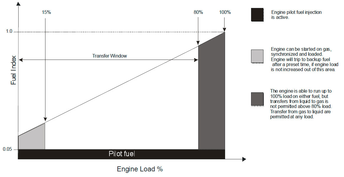
Fuel transfer window
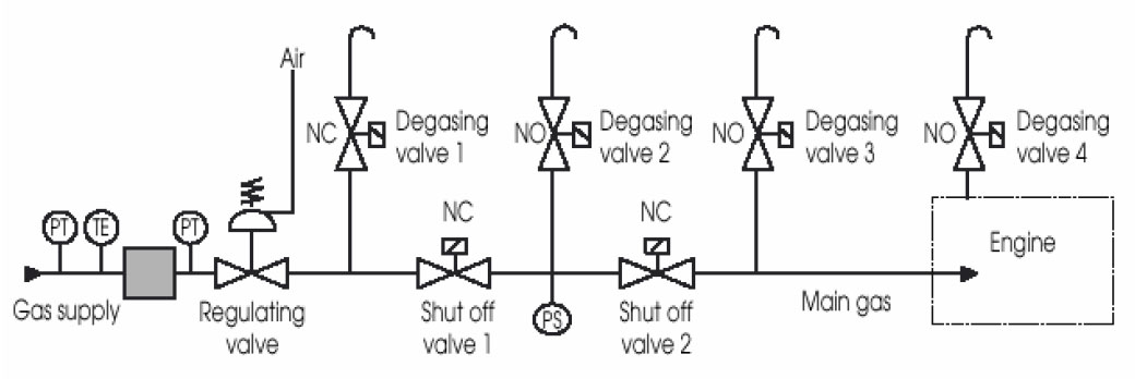
Gas feed system 50DF
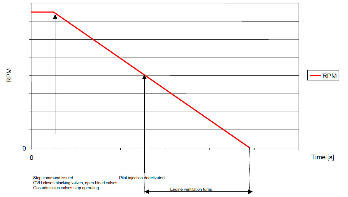
Stop of DF engine
Simple Hard Wired Interface
SHIP'S ALARM & MONITORING SYSTEM
INPUT:
- Engine common alarm
- UCP common alarm
- MCC common alarm
- Engine shutdown
- Unack. Alarm in WOIS
- Mod Bus data
MSB
INPUT:
- Engine ready to sync
- Trip breaker
- Engine running
OUTPUT:
- Gen load
- Breaker position
- Shutdown
- INC. speed
- DEC. speed
- Start
- Stop
- Start blocking
ESD SYSTEM
INPUT:
- Diesel mode
- Gas mode
- Engine running
- UCP de energised
- Emergency shutdown
OUTPUT:
- Emergency shutdown
- Gas operating mode blocked (>=25% LFL)
- ESD (Engine room de-energise) (>=50% LFU)
POWER MANAGEMENT SYSTEM
INPUTS:
- Engine ready to start
- Engine running
- Engine ready for gas transfer
- Max power available 4-20mA
- Engine speed 4-20mA
OUTPUTS:
- Gas operating mode
- Blackout mode
- Standby
UCP instruments
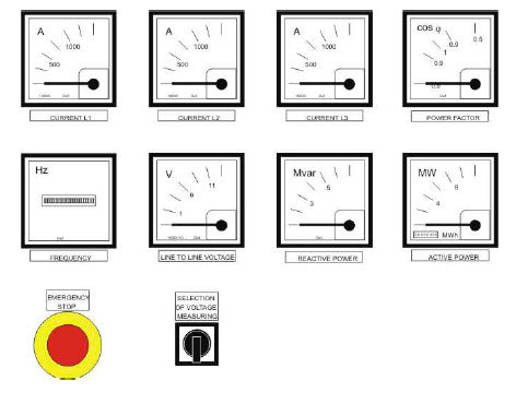
- 3 x Current red marked
- Cos FI
- Frequency
- Voltage + selector
- Mvar
- MW, (MWh)
Protection relays
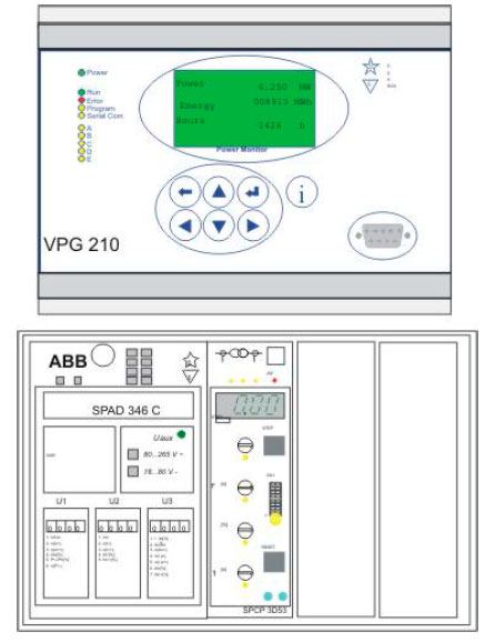
- Three over current stages
- Loss of excitation
- Reverse power
- Over / under voltage
- Under frequency
Option:
- Separate Differential relay
Local Control Unit
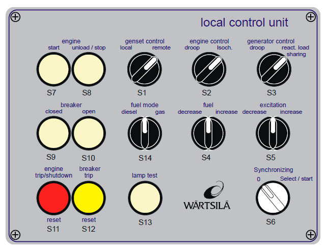
- Start / Stop genset
- Local / remote
- Speed control (doop/isoc)
- Gen Voltage (droop / react. Load s)
- Fuel mode (Diesel / Gas)
- Engine speed (increase / decrease)
- Gen voltage (increase / decrease)
- Open breaker
- Close breaker (dead bus)
- Shutdown, Gas / pilot trip reset
- Breaker trip reset
- Start synchronizing
Local display unit
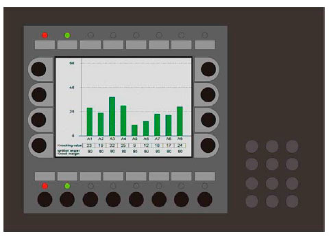
Displays:
- Genset status
- Start block’s
- Gas transfer permission
- Shutdown reason
- Gas trip reason
- Pilot trip reason
Control:
- Manual control of GVU during maintenance
Литература
www.wartsila.com

