Fuel filter / water separator
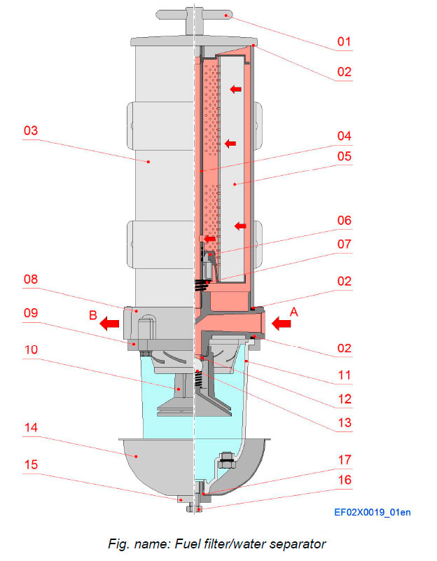
The filter protect precision engine components from dirt, rust, algae, asphaltines, varnishes, and especially water, which is prevalent in engine fuels. Filter remove contaminants from fuel using the following legendary three stage process:
STAGE 1 SEPARATION
As fuel enters the assembly, it moves past the internal check valve then through the turbine centrifuge where it flows in a spiralling direction, spinning off large particulates and water droplets. Being heavier than fuel, they fall to the bottom of the collection bowl.
STAGE 2 COALESCING
Small water droplets bead-up along and on the side of the internal components and on the surface of the conical baffle and cartridge element. When heavy enough, they too fall into the bottom of the collection bowl to be drained as needed.
STAGE 3 FILTRATION
Cartridge elements repel water and remove contaminants from fuel. Cartridge elements are waterproof and effective longer than water absorbing elements.
Water separator
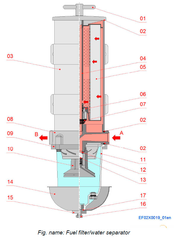
Components
- 01 T-handle
- 02 Gasket
- 03 Outer cylinder
- 04 Return tube
- 05 Filter element
- 06 Fuel shut-off valve
- 07 Spring
- 08 Body
- 09 Bowl ring
- 10 Turbine centrifuge
- 11 Bowl
- 12 Sealing
- 13 Check valve
- 14 Heat deflector shield
- 15 Bowl drain fitting
- 16 Bowl plug
- 17 Gasket
Pipe connections
- A Fuel inlet
- B Fuel outlet
Fuel oil filter
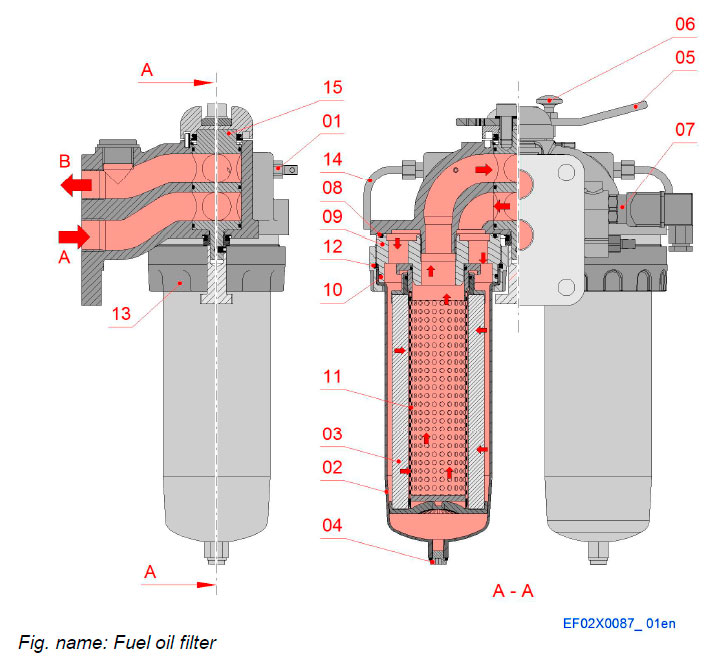
The filter is a duplex filter. By means of the three-way valve (15) the fuel flow can be guided to one side or the other, or to both sides in parallel. The direction of the flow appears from the mark on the filter housing. At normal operation, one or both sides of the filter can be used. When changing cartridges during operation one side can be closed. The fuel flows through a strainer core (11) and a cartridge (3) made of special paper material for filtering off small particles.
Components
- 01 Venting screw
- 02 Bowl
- 03 Filter cartridge
- 04 Drain plug
- 05 Handle
- 06 Locking knob
- 07 Indicator
- 08 O-ring
- 09 Adapter
- 10 O-ring
Components
- 11 Strainer core
- 12 Lock ring
- 13 Fastening ring
- 14 Bleeding pipe
- 15 Spool
Pipe connections
- A Inlet
- B Outlet
Safety valve for pilot fuel
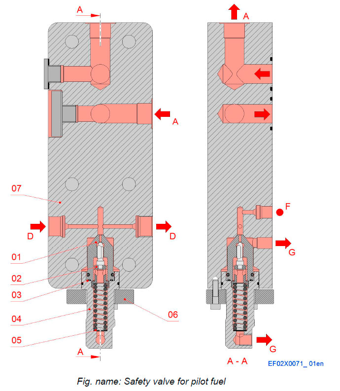
Components
- 01 Valve
- 02 Spindle
- 03 O-ring
- 04 Connection piece
- 05 Plates
- 06 Flange
- 07 Valve housing
Pipe connections
- A Pilot fuel inlet
- D Pilot fuel delivery
- F Connection for pressure sensor
- G Drain connection
Injection system
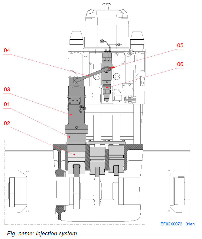
The injection system consists of a base for injection pump, pump tappet, an injection pump, a high pressure injection pipe, the connection piece and an injection valve. The system upraises the injection pressure.
Components
- 01 Base for injection pump
- 02 Injection tappet
- 03 Injection pump
- 04 High pressure injection pipe
- 05 Connection piece
- 06 Injection valve with pilot injection
Base and injection tappet assembly
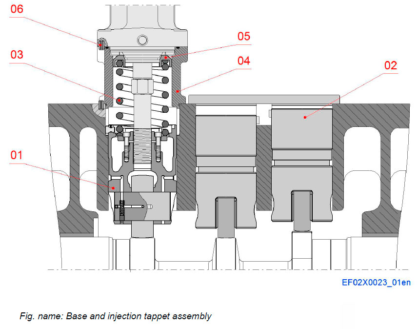
The injection valve mechanism consists of piston type injection tappet moving within the engine block.
The tappet movement follows the cam profile and transfers the movement through adjusting screw and pump tappet to the injection pump.
The inner part of mechanism is lubricated by engine oil.
Components
- 01 Injection tappet
- 02 Valve tappet
- 03 Spring
- 04 Base
- 05 Spring plate
- 06 Spring pin
Injection tappet
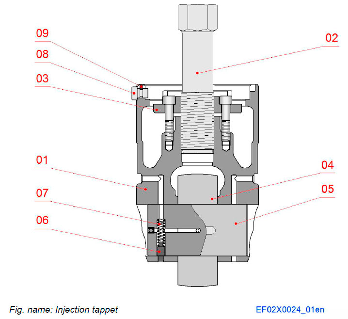
The injection mechanism consists of piston type valve tappet moving in bored guide of engine block.
The injection tappets movement follows the cam profile and thus transfers the movement to the injection pump.
The injection tappet is equipped with adjusting screw and securing plate.
Components
- 01 Tappet
- 02 Adjusting screw
- 03 Securing plate
- 04 Tappet roller
- 05 Roller pin
- 06 Locking pin
- 07 Spring
- 08 Guiding pin
- 09 Spring pin
Injection pump
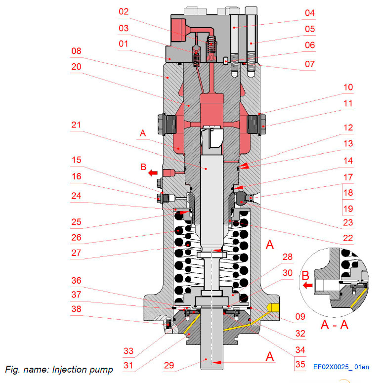
The injection pumps are one-cylinder pumps with builtin roller tappets. The element is of mono type. The drain fuel is led to a pipe system with atmospheric pressure outside the pump, or back to the low pressure circuit of the injection pump. Each injection pump is equipped with an emergency stop cylinder, which is coupled to an electro-pneumatic over speed protecting system.
The injection pump pressurises fuel to the injection nozzle. It has a regulating mechanism for increasing or decreasing the fuel feed quantity according to the engine load and speed. The injection pumps are governed by the governor.
The plunger, pushed up by the camshaft via the roller tappet and pulled back by the spring acting on the plunger, reciprocate n the element on a predetermined stroke to feed fuel under pressure.
Components
- 01 Connection piece
- 02 Main delivery valve
- 03 Constant pressure valve
- 04 Screw, (element)
- 05 Screw, (pump cover)
- 06 Cylindrical pin
- 07 Sealing ring
- 08 Housing
- 09 Retaining ring
- 10 Sealing ring
- 11 Erosion plug
- 12 Trust ring
- 13 O-ring
- 14 O-ring
- 15 Sealing ring
- 16 Plug
- 17 Locking screw
- 18 O-ring
- 19 Retaining ring
- 20 Pump element
- 21 Plunger
- 22 Regulating sleeve
- 23 Control rack
- 24 Spring plate
- 25 Shaft seal
- 26 Spring, outer
- 27 Spring, inner
- 28 Spring plate, lower
- 29 Pump tappet
- 30 Retaining ring
- 31 Bottom flange
- 32 O-ring
- 33 Flange
- 34 O-ring
- 35 Shaft seal
- 36 Screw
- 37 Washer
- 38 Screw
Connections
- A Fuel inlet chamber
- B Leak fuel
FUNCTION OF INJECTION PUMP
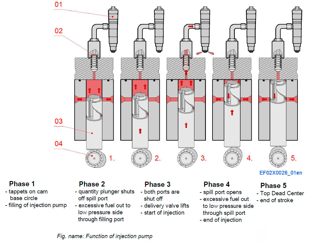
Function principle of injection pump is described in the figure.
According to the engine load, the amount of fuel injected is increased or reduced by turning the plunger a certain angel to change the helix position where the ports are closed on the up stroke and hence increasing or reducing the effective stroke. The fuel rack s connected to the regulating mechanism of the governor.
If the fuel rack is moved, the control sleeve in mesh with the rack s turned. Since the control sleeve acts on the plunger, the plunger turns with the control sleeve, thus the effective stroke changes and the injected fuel amount increases or decreases.
Components
- 01 Injection valve
- 02 Delivery valve
- 03 Quantity plunger
- 04 Cam shaft
Connection piece
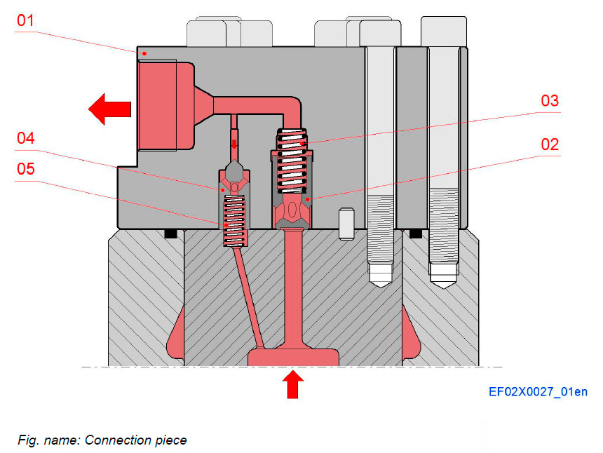
The main delivery valve functions as a delivery valve to control the fuel flow to the injectors and as a non return valve to avoid high pressure peaks from the injection pipes entering the pump chamber. The valve closes immediately when pressure starts to decrease in the pump chamber.
Constant pressure valve stabilizes the pressure pulsation in the injection pipes. Cavitation can be avoided and hydraulic stability will be improved.
When the main delivery valve is closed, pressure relief in the high pressure line then continues through the constant pressure valve. The rapid relief of the pressure in the injection valve is necessary to ensure rapid closing of the injection valve and to prevent dribble into the combustion chamber.
Components
- 01 Connection piece
- Main delivery valve
- 02 Delivery valve bush
- 03 Spring
- Constant pressure valve
- 04 Constant pressure spindle
- 05 Spring
Pneumatic STOP cylinder
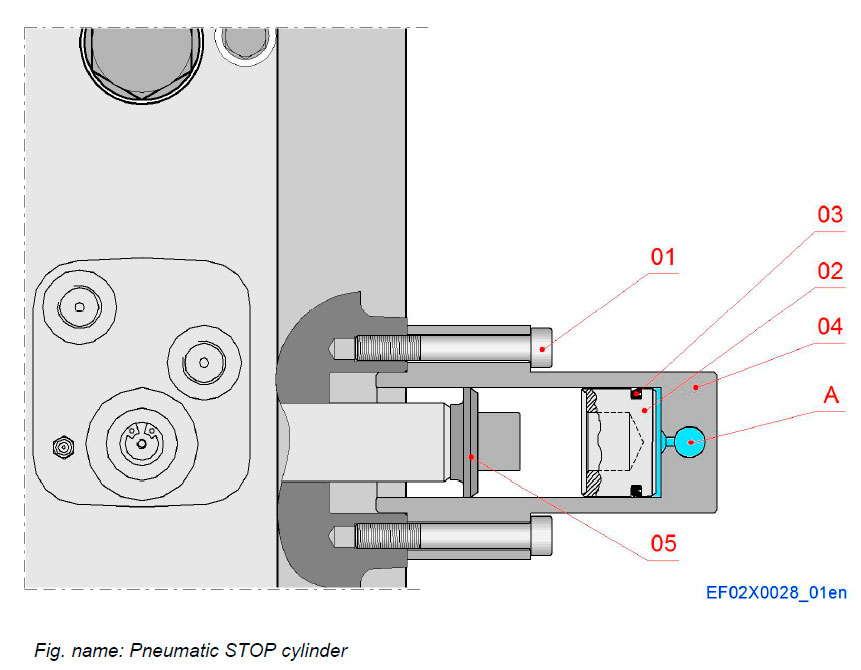
The pneumatic over speed trip device is integrated into injection pump and acts directly on the fuel rack.
Emergency stop cylinder pushes the control rack of the fuel amount plungers to the zero position using control air pressure when the electronic over speed control is activated or (depending on the installation) when an automatic shut-down system is activated.
Components
- 01 Screw
- 02 Piston
- 03 Shaft seal
- 04 Stop cylinder
- 05 Shim
Pipe connections
- A Control air
Main injection line
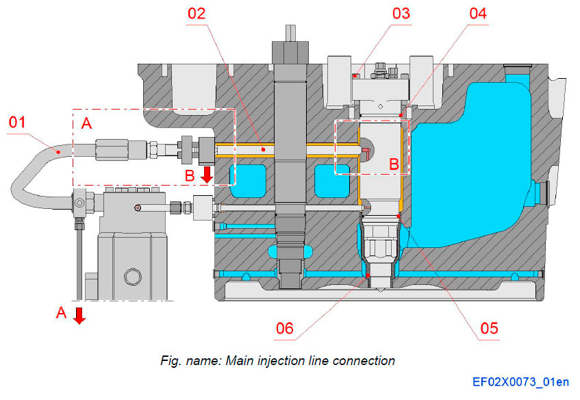
The main fuel injection line consists of two parts, a connection piece and a high pressure injection pipe. Connection piece is connected into the side of the nozzle holder, and the injection pipe with conical connection and seals with plain metallic surfaces.
The double wall injection pipes are delivered complete with connection nuts assembled.
Components
- 01 Main Injection pipe
- 02 Main connection piece
- 03 Tightening screw
- 04 O-ring
- 05 O-ring
- 06 Center sleeve
Pipe connections
- A Fuel leakage, injection pipe
- B Fuel leakage, injection valve
Main injection line
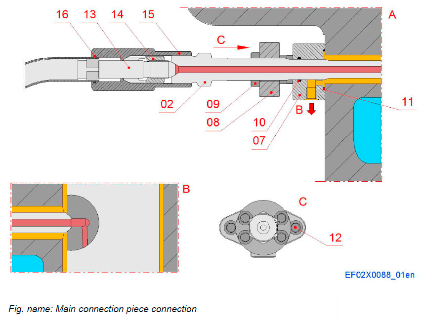
Components
- 02 Main connection piece
- 07 Connection flange
- 08 Flange
- 09 Tightening screw
- 10 O-ring
- 11 O-ring
- 12 Tightening screw
- 13 High pressure inner pipe
- 14 Clamping sleeve
- 15 Nut
- 16 O-ring
Pipe connections
- B Fuel leakage, injection valve
Injection valve
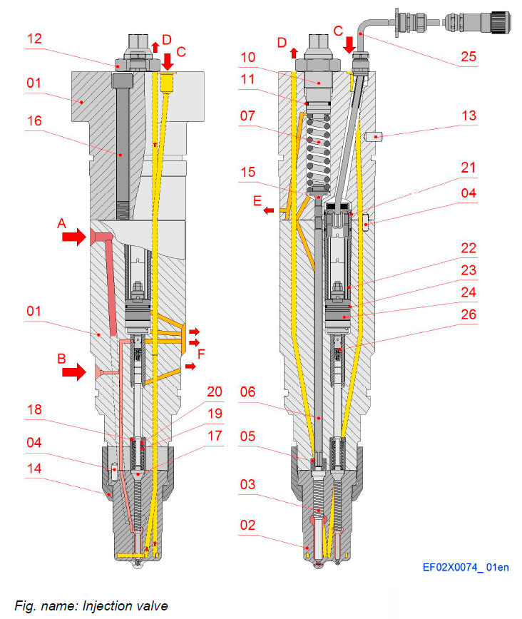
The injection valve is a combined pilot and main fuel oil injection valve, where the pilot injection is electronically controlled. The nozzle holder consists of a top body and a lower body, which contain the rods, springs, control valve and solenoid.
The nozzles receive high pressure main and pilot fuel through the injection lines and inject this fuel into the combustion chamber as a very fine spray.
Components
- 01 Holder body
- 02 Needle housing
- 03 Main nozzle needle
- 04 Cylindrical pin
- 05 Ring
- 06 Push rod
- 07 Spring
- 10 Adjusting screw
- 11 O-ring
- 12 Nut
- 13 Cylindrical pin
- 14 Nozzle nut
- 15 Push rod
- 16 Screw
- 17 Pilot nozzle needle
- 18 Bush
- 19 Compression spring
- 20 Distance ring
- 21 O-ring
- 22 Locking bush
- 23 O-ring
- 24 Solenoid
- 25 Cable
- 26 Pilot element assembly
Connections
- A Main fuel in
- B Pilot fuel in
- C Cooling oil in
- D Cooling oil out
- E Main leak fuel
- F Pilot leak fuel
PILOT VALVE
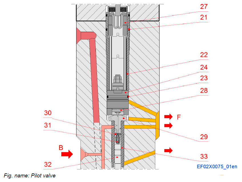
The pilot fuel pressure acts on both the pilot needle pressure step (opening force) and through an orifice on the pilot piston (closing force). The solenoid valve opens a drain port from the pilot cylinder and thus eliminates the pressure acting on the piston, and the fuel pressure acting on the needle forces the needle upwards. The drained fuel is led through borings to the clean fuel leakage system of the engine. A spring acting on the push rod keeps the pilot needle closed in event of loss of pilot fuel pressure.
System components
- 21 O-ring
- 22 Locking bush
- 23 O-ring
- 24 Solenoid
- 27 cable connection
- 28 Armature
- 29 Control element
- 30 Valve plate
- 31 Valve spring
- 32 Valve rod
- 33 Valve sleeve
Pipe connections
- B Pilot fuel inlet
- F Pilot fuel leak
PILOT VALVE
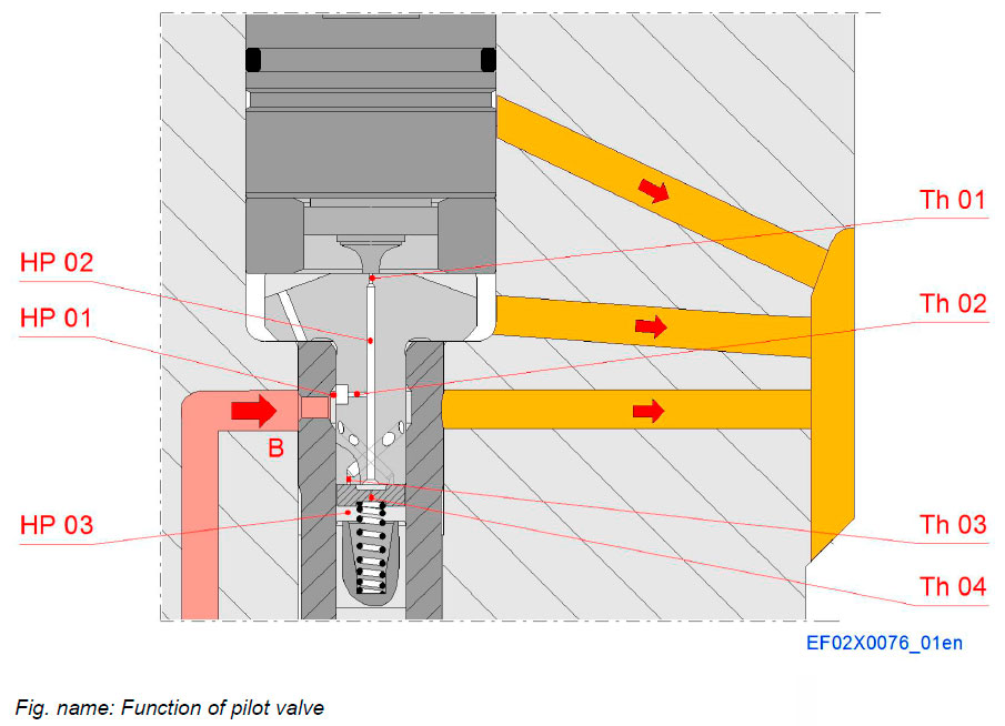
Opening of needle:
If solenoid is energized, armature moves upwards and opens throttle 1. Throttle diameter 1 is bigger than throttle diameter 2, so pressure in HP-space 2 and 3 will decrease. So needle in nozzle element will open, because of force surplus at pressure step of needle in nozzle element. Pressure in HP-space 1 is nearly constant. Throttle 3 is closed by valve plate.
Closing of needle in nozzle element:
If solenoid is de-energized, armature moves downwards, forced by a spring in the solenoid, and closes throttle 1. Fuel fills up HP-space 2. Because of force surplus valve plate is forced to move downwards and so throttle 3 is opened. That’s why HP-space 3 can be filled much quicker. So the needle can be closed much faster.
System components
- HP 01 Pressure space 1
- HP 02 Pressure space 2
- HP 03 Pressure space 3
- Th 01 Throttle 01
- Th 02 Throttle 02
- Th 03 Throttle 03
- Th 04 Throttle 04
Pressure regulating valve
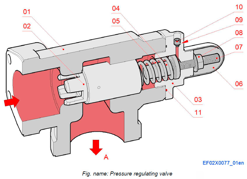
The valve is a directly controlled pressure limiting valve which is installed at the outlet of each engine to maintain the pressure of the circulating system at the correct and constant value.
The sliding piston (poppet) is pressed against the sealing face by a compression spring and separates the inlet connection of the valve from outlet connection while also sealing the bore. As soon as the operation pressure is adjusted by the adjusting screw, the sliding piston (poppet) releases the oil flow to the outlet. As the inlet pressure falls below the set pressure value, the valve closes. The spring chamber is pressure compensated by a borehole to the outlet. During valve start-up, the spring chamber must be expelled from possible air by releasing the venting screw.
Components
- 01 Housing
- 02 Sliding piston
- 03 Cover
- 04 Spring guide
- 05 Spring
- 06 Protecting cap
- 07 Set screw
- 08 Nut
- 09 Sealing ring
- 10 Venting screw
- 11 O-ring
Pipe connections
- A Fuel outlet
Литература
www.wartsila.com

