
WinGD originated from the diesel engine business of Sulzer Corporation in Winterthur (Switzerland), established in 1893 when the Sulzer Brothers signed an agreement with Rudolf Diesel for his new engine technology.
Sulzer started diesel engine manufacturing in 1903 in Winterthur. In 1986 the last diesel engine left the Winterthur facility.
Going forward to November 1990, Sulzer established its Diesel Engine & Diesel Power Plant Division as a separate company, New Sulzer Diesel Ltd.
In April 1997, New Sulzer Diesel Ltd. merged with Wärtsilä Diesel Oy to create Wärtsilä NSD Corporation which later became Wärtsilä Corporation. The Swiss company, Wärtsilä Switzerland Ltd., responsible for the low-speed, two-stroke engine within Wärtsilä, was merged with China State Shipbuilding Corporation (CSSC) in early 2015 and renamed Winterthur Gas & Diesel Ltd. (WinGD). In 2016, Wärtsilä Corporation transferred its remaining shares of WinGD to CSSC making WinGD 100% owned by CSSC.
The engine brand was changed from 'Wärtsilä' to ‘WinGD’. Today WinGD supports its engines with state-of the-art digital technologies, training and warranty services.
The WinGD RT-flex/X is basically a standard WinGD low-speed two-stroke marine diesel engine in which a common-rail system for fuel injection and exhaust valve actuation, and full electronic control of these engine functions, is employed instead of the traditional mechanical camshaft system.
The WinGD engines offer a number of interesting benefts to shipowners and operators:
- Smokeless operation at all operating speeds.
- Lower steady running speeds, in the range of 10-15 per cent nominal speed, obtained smokelessly through sequential shut-off of injectors while continuing to run on all cylinders.
- Reduced running costs through reduced part-load fuel consumption and longer times between overhauls.
- Reduced maintenance requirements, with simpler setting of the engine. The ‘asnew’ running settings are automatically maintained.
- Reduced maintenance costs through precise volumetric fuel injection control leading to extendable times between overhauls. The common-rail system with its volumetric control gives excellent balance in engine power developed between cylinders and between cycles, with precise injection timing and equalised thermal loads.
- Reliability is given by long-term testing of common-rail hardware in component test rigs.
- Higher availability owing to the integrated monitoring functions.
- High availability also given by the built-in redundancy, provided by the ample capacity and duplication in the supply pumps, main delivery pipes, crank-angle sensors, electronic control units and other key elements.
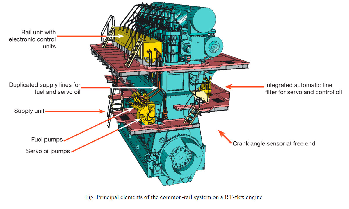
There are four principal elements in the WinGD common-rail system: the rail unit along the side of the cylinders, the supply unit on the side of the engine, a filter unit for the servo oil, and the integrated electronic control system, including the crank angle sensor.
List of abbreviations and explanations
- BEMP - Brake Mean Effective Pressure
- BSFC - Brake specific fuel consumption
- CSSC - China State Shipbuilding Corporation
- DENIS - Diesel Engine Interface Specification
- HMI-flexView - Human-Machine Interface
- ICU - Injection control units
- ICV - Injection control valve
- IMO - International Maritime Organisation
- TBO - Times between overhauls
- VCU - Valve control unit
- VEC - Variable exhaust valve closing
- VIT - Variable injection timing
- WECS - Wartsila Engine Control System
- WinGD - Winterthur Gas & Diesel Ltd
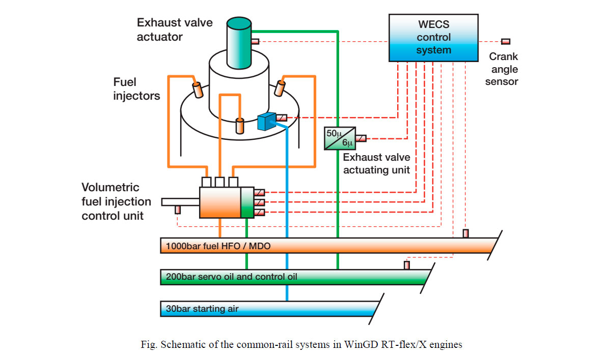
The RT-flex engines are thus equipped with common rail systems for:
- heated fuel oil at pressures 550-850 bar delivered by the fuel pumps of the supply unit. For each cylinder, there is an Injection Control Unit (ICU) installed on the fuel rail.
- servo oil at pressures 80-190 bar,delivered by the servo oil pumps of the supply unit, depending on the engine load. For each cylinder there is a Valve Control Unit. Exhaust valve actuator or valve control unit (VCU) installed on the servo oil rail. WECS activats the VCUs when exhaust valves are needed to be opened and closed.
- control oil at a constant pressure of 200 bar, delivered by the control oil pumps (only for RT-flex96C-B, RT-flex60 and RT-flex84T).
- engine starting air system.
Supply unit
Fuel and servo oil are supplied to the common-rail system from the supply unit which is driven through gearing from the engine crankshaft.
In the first few RT-flex engines, the supply unit is on the exhaust side of the engine so that it could be lower down without interfering with access to the crankcase. However, for all subsequent engines, the location of the supply unit has since been standardised on the front of the engine (on the same side as the rail unit) and at about mid height. This keeps the engine ‘footprint’ small so that the engines can be located far aft in ships with fine afterbodies.
The supply unit is naturally at the location of the gear drive: at the driving end for five- to seven-cylinder engines, and at the mid gear drive for greater cylinder numbers.
The supply unit has a rigid housing of nodular cast iron. The fuel supply pumps are arranged on one side of the drive gear and the hydraulic servo-oil pumps are on the other side. This pump arrangement allows a very short, compact supply unit with reasonable service access. The numbers, size and arrangement of pumps are adapted to the engine type and the number of engine cylinders.
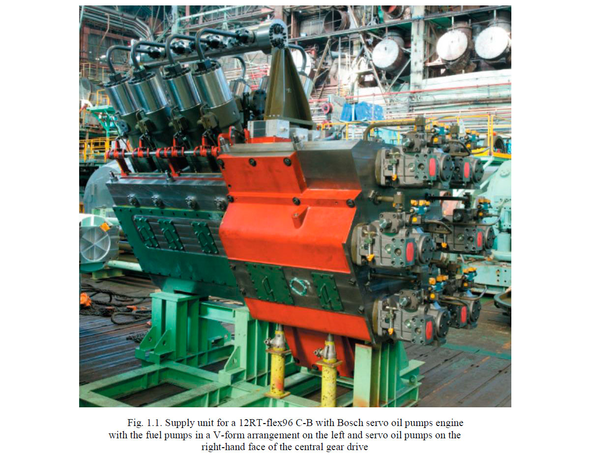
For RT-flex58-96, the supply unit is equipped with four to eight fuel supply pumps arranged in V-form. The RT-flex50 supply unit, however, has just two or three supply pumps in-line.
Two sizes of fuel pumps are employed for all RT-flex engines, both based on the well-proven injection pumps used in Sulzer Z-type medium-speed four-stroke engines though with some adaptations to suit their function as supply pumps and to raise their volumetric efficiency up to a very high degree. For RT-flex58-68, the fuel pump elements are based on the injection pumps of Sulzer ZA40S engines, while the RT-flex84-96 pumps are based on the injection pumps of the Sulzer ZA50S engine type.
The fuel supply pumps are driven through a camshaft with three-lobe cams. This camshaft cannot be compared with the traditional engine camshaft. It is very short and much smaller diameter, and is quite differently loaded. There is no sudden, jerk action as in fuel injection pumps but rather the pump plungers have a steady reciprocating motion. With tri-lobe cams and the speed-increasing gear drive, each fuel supply pump makes several strokes during each crankshaft revolution. The result is a compact supply unit.
The servo oil pumps are driven by individual pinions, having a „mechanical fuse“ (reduced diameter in pinion), in order to protect the gear drive in case of a pump seizure. The servo oil pump gearwheel is hydraulically fitted as well.
Two designs of camshaft are employed. For RT-flex50-68 it is manufactured in one piece. For RT-flex84-96, the camshaft is assembled from a straight shaft on to which the tri-lobe cams are hydraulically press fitted. This latter form of construction has been used for decades in Sulzer Z-type engines. It is extremely service friendly and minimizes maintenance cost. The camshaft bearings have an aluminium running layer.
The fuel delivery volume and rail pressure are regulated according to engine requirements through suction control with helix-controlled filling volume regulation of the fuel supply pumps. Suction control was selected for its low power consumption as no excess fuel is pressurized.
The roller guide pistons contain the floating-bush bearings for the rollers as they are used on all Sulze RTA- and Z-type engines. Owing to the moderate accelerations given by the tri-lobe cam shape, the specific loads of roller bearings and pins as well as the Hertzian pressure between cam and roller are less than for the original pumps in ZA40S and ZA50S engines.
For every individual fuel pump element of the supply unit, the roller can be lifted off the cam, blocked and manually taken out of service in case of difficulties.
Since the supply unit, i.e. fuel pumps and servo oil pumps have no timing, means they just supply fuel or oil, the camshaft doesn‘t have to have a determined position compared to crankshaft. However the position of the cams relative to each other must be respected.
The fuel pumps deliver the pressurized fuel to an adjacent collector from which two independent, double walled delivery pipes lead upwards to the fuel rail. Each delivery pipe is dimensioned for full fuel flow. The collector is equipped with a safety relief valve set to 1250 bar. The rail is heated by a trace heating piping system.
An equivalent arrangement of a collector and duplicated independent, double-walled delivery pipes is employed for the servo oil supply.
Servo oil
Servo oil is used for exhaust valve actuation and control, cylinder lubricating system and fuel injcection control unit. It is supplied by a number of swash plate-type axial piston hydraulic pumps mounted on the supply unit. The pumps are of standard proprietary design and are driven at a suitable speed through a step-up gear. The working pressure is controlled to allow a desied speed of exhaust valve opening at different loads. At higher loads the exhaust valve has to overcome a higher cylinder pressure, so that the higher force is required for opening. The servo oil rail contains fine filtered (6-micron/25-micron) high pressure servo oil, ~ 80-220 bar, delivered by the servo oil pumps of the supply unit, depending on engine load. The nominal operating pressure is up to 220 bar. The number and size of servo oil pumps on the supply unit depend on the engine speed and number of engine cylinders. There are from two to six servo oil pumps per engine.
The oil used in both the servo and control oil systems is standard engine system lubricating oil, and is simply taken from the delivery to the engine lubrication system. The oil is drawn through a 6 or 25-micron automatic self-cleaning fine filter to minimise wear in the servo oil pumps and to prolong component life.
After the fine filter, the oil flow is divided, one branch to the servo oil pumps and the other to the control oil pumps.
Control oil
Control oil is supplied at a constant 200 bar pressure at all engine speeds by two electrically-driven oil pumps, one active and the other on standby. Each pump has its own pressure-regulating valve and safety valve attached.
The control oil system involves only a small flow quantity of the fine filtered oil. The control oil serves as the working medium for all rail valves of the injection control units. The working pressure of the control oil is maintained constant to ensure precise timing in the ICU. It is also used to prime the servo oil rail at standstill thereby enabling a rapid starting of the engine. Control oil system is used only on old models of RT-flex60/84 and 96. The latest RT-flex and all X type engines use servo oil instead.
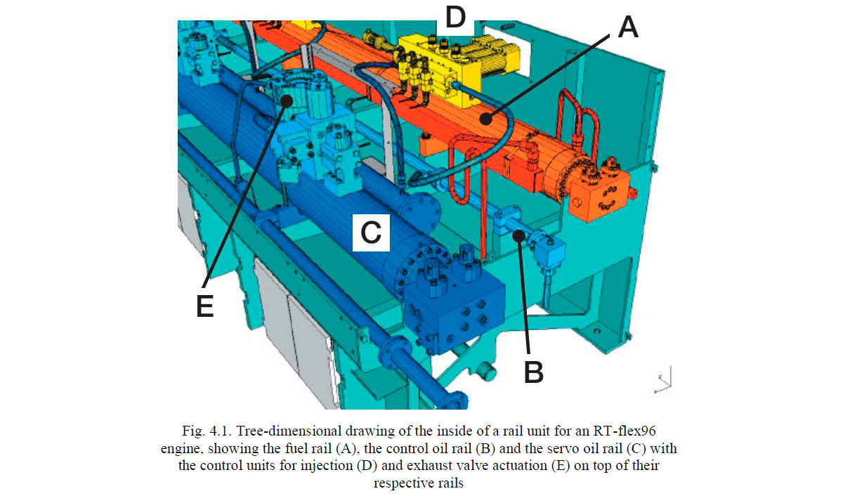
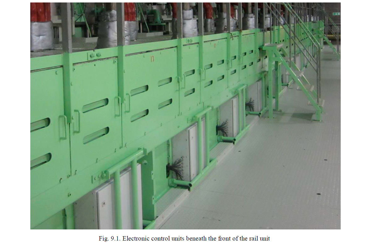
Rail unit
The rail unit is located at the engine’s top platform level, just below cylinder cover level. It extends over the length of the engine. It is fully enclosed but has good maintenance access from above and from the front. The rail unit contains the rail pipes and associated equipment for the fuel, servo oil and control oil systems. The starting air system is not included in the rail unit.
For engines with up to eight cylinders, the rail unit is assembled as a single unit. With greater numbers of cylinders, the engines have a mid gear drive and the rail unit is in two sections according to the position of the mid gear drive in the engine. Both rail-sections (forward/aft) for fuel-, servo- and control oil are connected by high pressure pipes.=> Same pressure in the related rails of both halves.
The fuel common rail provides storage volume for the fuel oil, and has provision for damping pressure waves. There is no need for energy storage under gas pressure. The volume of the common-rail system and the supply rate from the fuel supply pumps are such that the rail pressure is very stable with negligible pressure drop after each injection.
The common rail system is designed with very high safety margins against material fatigue. The fuel rail pipe for instance has a very special inner shape to keep the stress amplitude in cross-bored drillings remarkably low. The fact that, by definition, common rails have almost constant pressure levels further increases the safety against high cycle fatigue cracking compared to conventional injection and actuator systems with high pressure cycles.
The high-pressure rail is trace heated from the ship’s heating system, using either steam or thermal oil.
The fuel rail contains high pressure fuel of ~ 550-850 bar delivered by the fuel pumps of the supply unit. For each cylinder, there is an injection control unit.
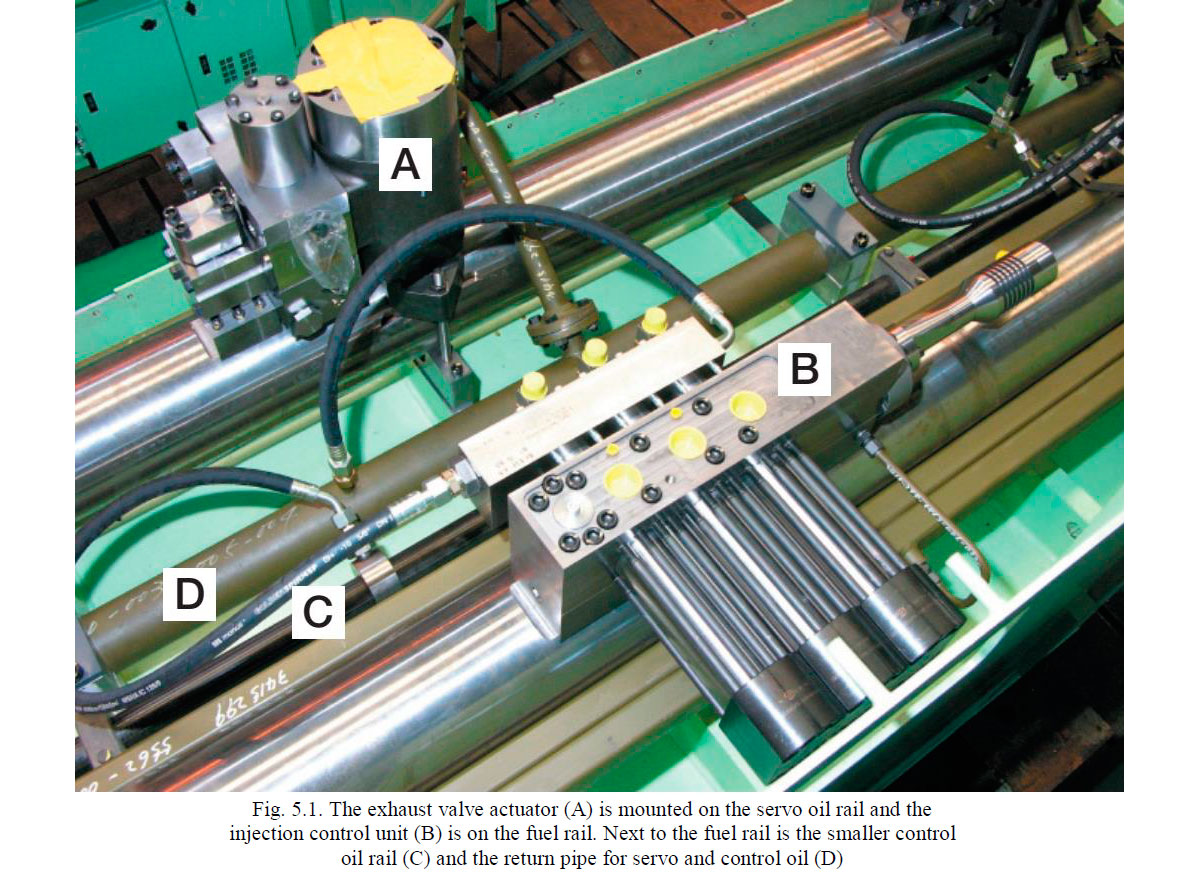
Injection control unit
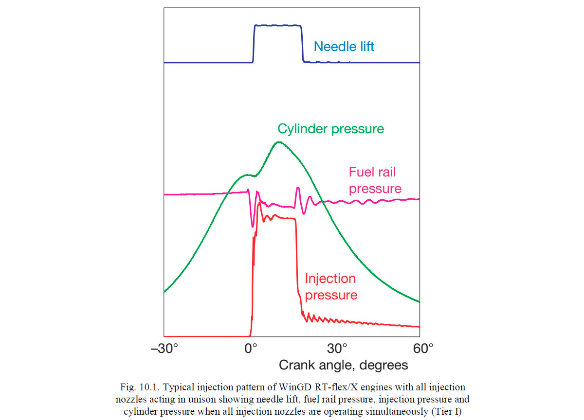
Fuel is delivered from the common rail to the injection valves through a separate ICU for each engine cylinder. The ICU regulates precisely the timing of fuel injection, accurately controls the volume of fuel injected, and sets the shape of the injection pattern. The ICU has an injection control valve (ICV) and an electro-hydraulic rail valve (bi-stable rail valve) for each fuel injection valve. The rail valves receive control signals for the beginning and end of injection from the respective electronic unit of the WECS (Wärtsilä Engine Control System).
There are three fuel injection valves in each engine cylinder except for the RT-flex48-50 which has two. The fuel injection valves are the same as those already employed in RTA engines, and are hydraulically-operated in the usual way by the high-pressure fuel oil. Each fuel injection valve in a cylinder cover is independently controlled for the respective cylinder so that, although all the injection valves in an individual cylinder normally act in unison, they can also be programmed to operate separately as necessary e.g. for sequential injection.
The individual ICU are mounted directly on the rail pipe.
The common-rail system is purpose-built for operation on just the same grades of heavy fuel oil as are already standard for Sulzer RTA-series engines. For this reason, the RT-flex system incorporates certain design features not seen in other common-rail engines using middle distillate diesel oils. The key point is that, in the ICU, the heated heavy fuel oil is isolated from the precision rail valves.
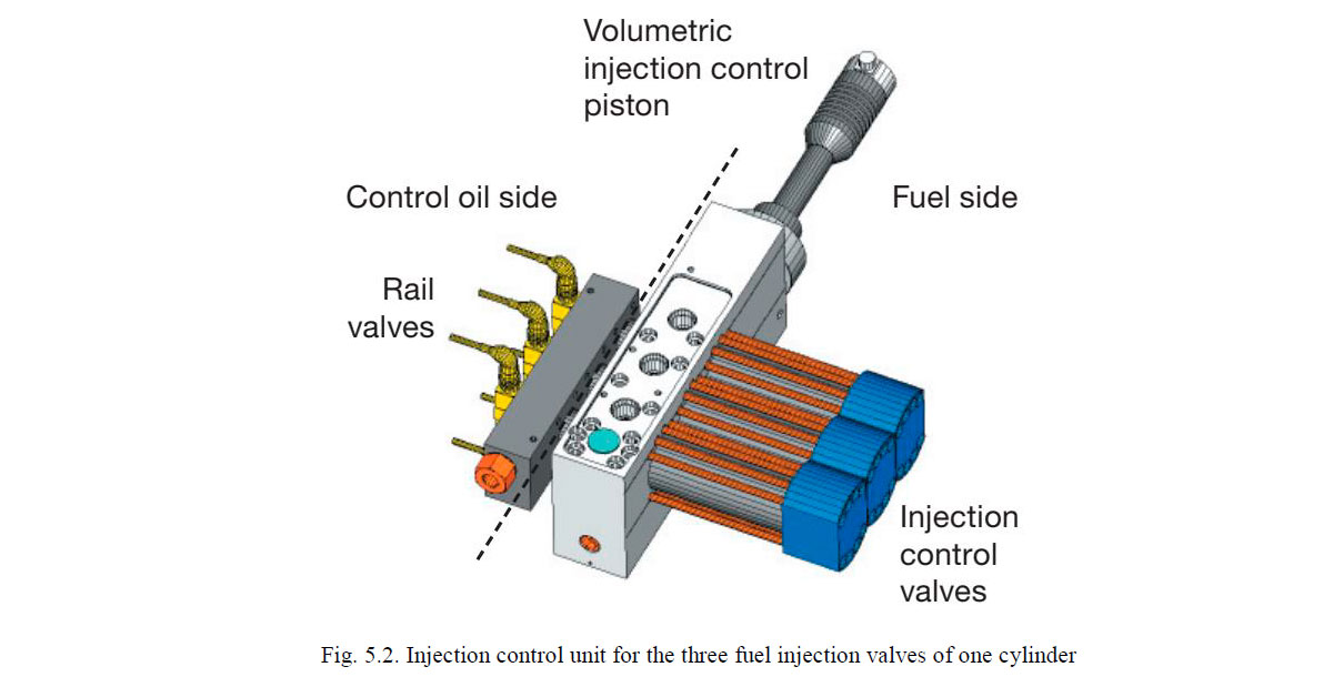
The rail valves are bi-stable solenoid valves with an extremely fast actuation time. To achieve the longest possible life time, the rail valves are not energised for more than 4 ms. This time is sampled, monitored and limited by the WECS-9520. The valves’ bi-stability allows their position and status to be reliably controlled. Each ICU is pre-controlled by 2 or 3 rail valves to open or close the way for fuel from the rail to the injection nozzles.
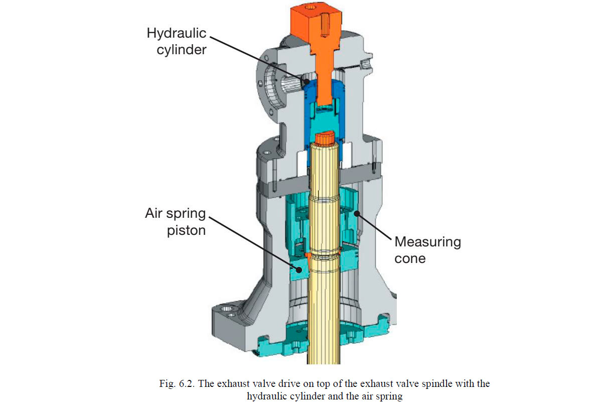
Exhaust valve control
The exhaust valves are operated by a hydraulic ‘push rod’, being opened by hydraulic oil pressure and closed by an air spring, as in the Sulzer RTA engines with mechanical camshafts. But for RT-flex/X engines the actuating energy now comes from the servo oil rail. There is one exhaust valve actuator (also known as the partition device) for each cylinder.
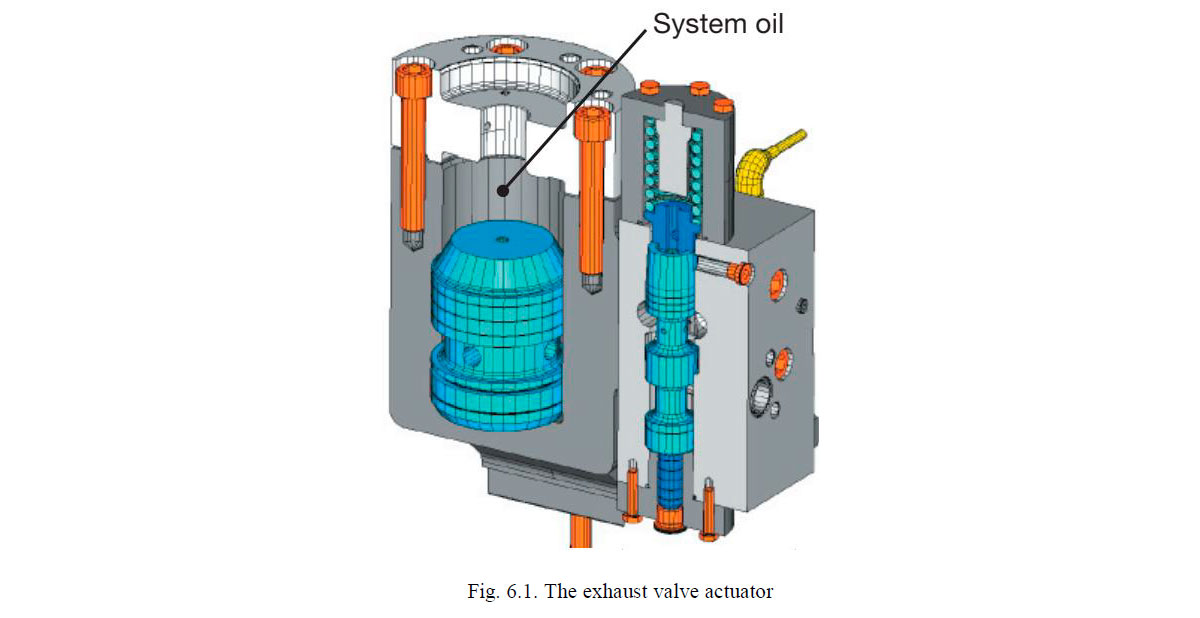
In the exhaust valve actuator, fine-filtered servo oil acts on the underside of a free-moving actuator piston, with normal system oil above the actuator piston for valve actuation. The adjacent hydraulic control slide is precisely activated by a rail valve and controls the flow of servo oil to the actuator piston so that the exhaust valve opens and closes at precisely the correct time with appropriate damping. The exhaust valve actuator employs the same rail valves as are used for the ICU.
The exhaust valve drive on top of the valve spindle is equipped with one or two analogue position sensors to provide a feedback on valve operation to the WECS-9520.
The electronically-controlled actuating unit for each cylinder gives full flexibility for exhaust valve opening and closing patterns. At the same time, the actuating unit provides a clear separation of the clean servo oil and the normal system oil. Thus the exhaust valve hydraulics can be serviced without disturbing the clean servo oil circuit.
Operating pressures and system energy
The normal operating pressure for the fuel rail range set to 1000 bar. It is lowered for the best compromise between BSFC (brake specific fuel consumption) and NOX emissions according to the respective engine load and to keep the parasitic energy demand low.
It was determined years ago by engine tests in Winterthur that, under steady load conditions, the influence of fuel injection pressure on specific fuel consumption in low-speed engines diminishes with increasing injection pressure. Thus, higher fuel injection pressures than are presently used in large two-stroke low-speed engines have no real benefit. Should an increase become necessary in the future, for instance in combination with other measures to reduce NOX emissions, the RT-flex/X system is ideal to cope with it. The additional, parasitic system energy would be very limited indeed, as the increase is about proportional to the pressure increase.
Exhaust valve actuation requires a high volume flow of oil. With an appropriately stepped hydraulic piston diameter on the valve spindle both proper valve movement and low parasitic power could be achieved at the same time. Additionally, the servo oil pressure of 220 bar nominal is variably adapted to the minimum requirement over engine load to ensure a proper function and minimal power demand.
Starting air system
The starting air system of RT-flex/X engines is very similar to that in Sulzer RTA engines, except that its control is incorporated into the WECS-9520. The starting air system, however, is installed outside the rail unit to facilitate overhaul access.
Electronic control
All functions in the RT-flex/X system are controlled and monitored through the WECS-9520. This is a modular electronic system with separate microprocessor control units for each cylinder, and overall control and supervision by duplicated microprocessor control units. Two modules provide the interface for the electronic governor, the shipboard remote control system, safety system and alarm and monitoring systems. The microprocessor control units, or electronic control modules, are mounted directly on the engine, either on the front of the rail unit or adjacent to it.
An essential and the most important input signal for WECS-9520 is the engine crank angle possition. This is measured very accurately by two absolute encoders driven from a stub shaft on the free end of the crankshaft. The two ancoders are driven by toothed belts so that axial and radial movements of the crankshaft are not passed to the sensors. The sensors are able to give the absolute crank angle position immediately when electrical power is applied.
At present RT-flex/X engines are being equipped with the WECS-9520 control system.
The system provides simple communication with the ship automation system and easier wiring for the shipbuilder. Only one electronic module is used through out the new system, and there are fewer equipment boxes which are also of simple, standard design. The functionality of WECS-9520 is similar and based on WECS-9500 system.
WinGD RTA and RT-flex/X engines have standardized interfaces (DENIS) for remote control and safety systems.The remote control and safety systems are supplied to the ship by a variety of approved manufacturers and DENIS (Diesel Engine Interface Specification) defines the interface between the engine-mounted equipment and the shipboard remote control and safety system.
With RT-flex/X engines, the remote control system sends engine manoeuvring commands to the WECS-9520. The remote control processes speed signals from the engine order telegraph according to a defined engine load program and fuel limiters, and generates a fuel command signal for the WECS-9520 according to DENIS.
The safety system function in RT-flex/X engines is basically the same as in conventional RTA engines, except that it has additional inputs for WECS slowdown and, WECS shutdown signals, and some outputs to theWECS system.
Reliability and redundancy
Reliability and safety have the utmost priority in the RT-flex/X system. Although particular attention is given to the reliability of individual items of equipment in the RT-flex/X system, the common-rail concept allows for increased reliability and safety through its inherent redundancy.
High-pressure fuel and servo-oil delivery pipes, the electrically-driven control oil pumps, and essential parts of the electronic systems are duplicated for redundancy. The duplicated high-pressure delivery pipes have stop cocks at both ends to isolate any failed pipe. Each single pipe is adequate for the full delivery. All high pressure pipes are double-walled for safety.
With a more traditional injection arrangement of one fuel high-pressure pump to each cylinder, a failure of one pump leads to the loss of that cylinder and the imbalance in engine torque requires a drastic power cut. In contrast, with the RT-flex/X system in which all high-pressure supply pumps are grouped together and deliver in common to all cylinders, the loss of any pumps has much less effect.
Indeed with larger RT-flex/X engines having several fuel pumps and several servo oil pumps there can be adequate redundancy for the engine to deliver full power with at least one fuel pump and one servo oil pump out of action. Should further pumps be out of action, there would be only a proportional reduction in power.
Every injection nozzle is independently monitored and controlled by the WECS. In case of difficulties, such as a broken high pressure line or a malfunctioning injector, the affected injection valve can be cut out individually without losing the entire cylinder.
The injection control unit ICU hydraulically excludes the injection of an uncontrolled amount of fuel. During the entire working cycle of the metering cylinder, there is never a direct hydraulic connection between fuel rail and the injectors. The maximum injection quantity is limited to the content of the metering cylinder as the travel of the metering piston is monitored. Maximum amount of fuel in ICU is aproximatly 130% fuel needed to for the full engine power. If the travel of the metering piston should be measured as out of range, the subsequent injections of that ICU will be suppressed and an engine slow-down activated.
The ICU also serves as a flow fuse: if the metering piston should travel to its physical limit, it cannot return hydraulically and no further injection would be possible until it is reset.
If the stroke measuring sensor fails, the WECS system switches the ICU to a pure time control and triggers the signal based on the timing of the neighbouring cylinders.
Two redundant crank angle sensors measure the absolute crank angle position which is evaluated through WECS. WECS is able to decide which sensor to follow in case of a discrepancy. The good sensor is check with a TDC signal. Maximum allowed difference between the sensors is 1 dgr for alarm, 5 dgr engine shutdown.
The WECS main controller and all essential communication interfaces such as CAN-bus cablings are duplicated for redundancy. WECS monitors the momentary position of each rail valve for proper function of each cycle before starting the next.
HMI- flex VIEW-9520
The flex View-9520 window is divided in two separate main-cards where different sub-cards can be select from the menu row on top of each card.
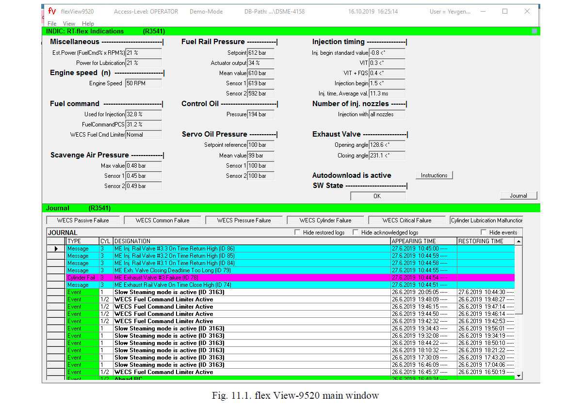
The two standard cards “Indic” and “Journal” are shown by default when the program is started. These two cards show all necessary data for the average daily use at sea or during manoeuvring.
- “Indic”(-ation) displays the actual engine speed, fuel command, common rail pressures and some general injection and exhaust valve timing data.
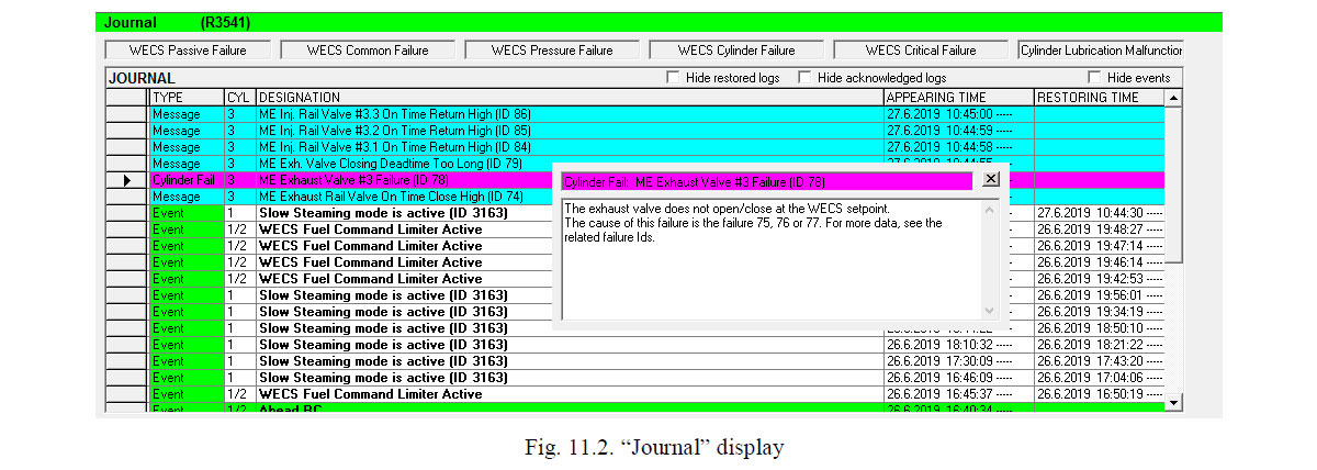
- “Journal” displays engine related failures and indications with time stamps for occurrence, acknowledging time and restoring time. For a quick reference the different indication groups have a colour code for easy separation of the groups.
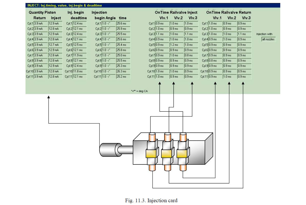
The amount of injected fuel is measured by the fuel quantity sensor in the ICU.
Each injection measurement starts at a return value and ends at a injection value corresponding to the given fuel command.
- The Injection begin dead time between sending a WECS-9520 command and the real injection begin is shown in the next column.
- Injection begin angle indicates the actual crank angle at injection begin and the duration time of the injection is shown in the next column.
- In the On Time Open / Close columns, flex View indicates the switch time that it takes to switch the rail valves over from one state to the opposite state. Times above 3,5 ms generally point out a rail valve failure.
- These indications help troubleshooting normal and static injection system failures.
For dynamic failures, the injection curve trend gives more detailed feedback.
On Exhaust Valve Card
- The Open Pos. & Close Pos. Sensor 1/2 columns show the valve stroke as a mA signal. A lower value indicates an open valve in the left columns, where as a higher value indicates a closed valve in the right columns of this card section.
- The “Deadtime” between WECS-9520 command and begin of the opening / closing stroke is indicated in the columns for each valve and movement (open/close). This is the time delay between the command for opening / closing and the beginning of the valve stroke into the corresponding direction.
- The “On” Time Open / Close columns indicates the switch time that it used to switch the rail valves over from one state to the opposite state. Times above 3,5 ms generally point out a rail valve failure.
- These indications help troubleshooting normal and static exhaust valve system failures. For dynamic exhaust valve failures, the exhaust valve curve trends give more detailed feedback.
Benefits from the WinGD RT-FLEX/X system
At its heart, the WinGD RT-flex engine is the same reliable, basic engine as the existing Sulzer RTA engine series. The power ranges, speeds, layout fields and full-power fuel consumptions are the same for both engine versions.
For shipowners, the principal benefits of WinGD RT-flex/X engines with their electronically-controlled common rail systems are:
- Reduced part-load fuel consumption.
- Smokeless operation at all running speeds.
- Very low, stable running speeds at about ten percent nominal speed.
- Easy engine setting for less maintenance.
- Longer times between overhauls (TBO) expected, primarily through better load balance between cylinders and cleaner combustion at all loads.
Low exhaust emissions
A clearly visible benefit of WinGD RT-flex engines is their smokeless operation at all ship speeds. It helps give a‘green’ image.
This was well demonstrated in the testing of the first RT-flex/X engine and during the sea trials of m/v «Gypsum Centennial» (present CSL Frontier). The superior combustion performance with the common-rail system is achieved by maintaining the fuel injection pressure at the optimum level right across the engine speed range. In addition, selective shut-off of single injectors and an optimised exhaust valve timing help to keep smoke emissions below the visible limit at very low speeds.
The precision and flexibility in engine setting givenby the RT-flex/X system facilitates compliance with the NOX regulation of Annex VI of the MARPOL 73/78 convention, usually referred to IMO NOX regulation.
The flexibility of the RT-flex/X engines will also allow alowering of NOX emissions if the corresponding increase in BSFC is acceptable. With common-rail injection, a wide variety of injection patterns can be generated. The injected quantity of fuel can be divided, for pre-injection, triple injection, etc. The WinGD RT-flex/X engine, with its individual fuel valve control, also has the unique ability to vary individually the injection timing and sequence between the three fuel injectors in each cylinder and thus to generate a tailor-made heat release.
In engine tests, this degree of flexibility has proved useful to reach NOX emissions of 20 percent below the IMO NOX limit with a moderate BSFC increase of 2.3 percent.
Very slow running
WinGD RT-flex/X engines have also demonstrated their ability to run stably at very low speeds, lower than engines with mechanically-controlled injection.
They can run without smoking at about ten per centnominal speed. This makes for easy ship handling when maneuvering or in river and canal passages.
Such slow running was well confirmed in service in m/v «Gypsum Centennial». Slow running was taken to a new ‘low’ during the testing in May/June 2004 of the first 12-cylinder RT-flex 96C engine. Owing to its number of cylinders, it could run steadily at just seven revolutions per minute.
The very slow running is made possible by the precise control of injection, together with the higher injection pressures achieved at low speed, and shutting off injector sat low speeds. Reducing the number of injection valves in operation makes injection of the reduced fuel quantities more efficient, especially as the injection pressure is kept up to a higher value than in a mechanically-injected engine at the same speeds.
Shutting off injectors provides more stable operation with better distribution of engine load and thermal loads than if very slow running was to be achieved by cutting out whole cylinders. Shutting off injectors is enabled by the separate control of individual fuel injection valves. This feature is unique to WinGD RT-flex/X engines. Usually the injection valves operate in unison but, as the engine speed is reduced, one injection valve can be shut off and at a lower speed a second injection valve can be shut off. Thus at minimum speed, the engine runs on all cylinders but with just one injection valve in each cylinder.
If the RT-flex/X engine then runs for a period in single injector operation, the electronic control system switches between the three injection valves in a cylinder so that the thermal load is equalised around the combustion chamber.
Fuel consumption flexibility
Sulzer RTA engines have always been highly competitiven in fuel consumption right across the load range owing to the use of variable injection timing (VIT). Variable exhaust valve closing (VEC) was also added in RTA84T engines in 1991 to reduce further the part-load BSFC.
These benefits have already been carried over to the electronically-controlled common-rail systems of the RT-flex/X engines.
At the first stage of development of RT-flex/X engines, however, the main objective has been to achieve the same performance standards as are achieved in the mechanical-camshaft engines, particularly with respect to power, speed, fuel consumption, exhaust emissions, cylinder pressures, etc. Thus the curves of brake specific fuel consumption of the first RT-flex/X engines have been the same as with corresponding RTA engines, or perhaps slightly lower in the part-load region. As the fuel injection pressure at part-load is kept higher with the common-rail injection system, combustion is sufficiently better to have a beneficial effect on fuel consumption inpart-load operation.
An alternative fuel consumption curve was introduced with Delta Tuning to provide even lower BSFC at loads less than 90 percent full load. For both the original (Standard) and Delta Tuning curves, the RT-flex/X engines comply with the IMO NOX regulation.
The question, of course, arises as to why the BSFC could not be lowered at all engine loads and speeds. It is technically possible to do so. With RT-flex/X engines all the relevant parameters can be continuously varied so that the engine can follow any specified BSFC curve as engine load and speed are varied. Yet there is a limitation because of the need to comply with the IMO NOX regulation and the inevitable trade-off between lower fuel consumption and greater NOX emissions. This explains the shape of the new BSFC curve given by Delta Tuning. The BSFC is lowered in the mid- and low-load range, there by increasing the NOX emission levels at those load points, but then has to be increased at high engine loads (90-100 percent load) for a compensating reduction in NOX levels.
Delta Tuning was first applied in the first Sulzer 8RT-flex96C engine which completed its official shop teston 9 April 2004.
Presently all new engines have four main tunings: Standard, Delta, Low load, Delta Bypass, each with possible low torsional viblatio variants:
- Standard Tuning: Optimized BSFC for engine load above 90%.
- Delta Tuning: Optimized BSFC for engine load between 75% to 90% load.
- Delta Bypass Tuning: Optimized for increasing steam production above 50% load; lower BSFC below 50% load compared to delta tuning.
- Low Load Tuning: Optimized BSFC for engine load below 75% load.
- Low-TV Tuning: Active below 25% load. Reduce gas excitation(smaller or no damper).
Литература
Двигатели WinGD типа RT-FLEX / X с электронным управлением - С. А. Карьянский, Е. М. Оженко [2019]