Crankshaft is the backbone of a 2-stroke engine. Technically, it’s a long and heavy part which undergoes severe fluctuating loads because of the gas pressure generated in the combustion chamber and high bending and torsional loads from heavy moving objects (piston, connecting rod etc.)
The crankshaft is built such that the crank angle of one unit lies at an angle different than that of the adjacent unit. The difference in angles depends on the number of units and strokes of the engine.
Types of Crankshaft
Following are four main types of crankshafts used in marine engines depending on the construction methods:
Fully Forged: In this method, the full crankshaft is a single piece, forged in a casting. The disadvantage of such type of crankshaft is the chance of twisting or bending.
Fully Built: In this type, all the components of the crankshaft i.e. crank pin web and journal pin are manufactured separately in steel casting. They are then shrink-fitted together to form a single unit.
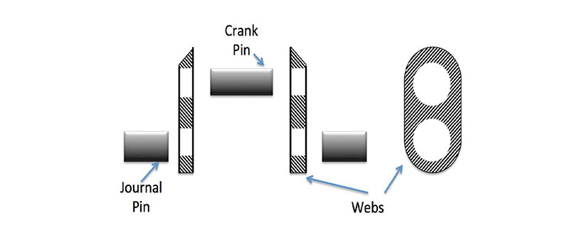
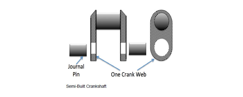
Semi Built: Instead of all components, only journal pin and crank throw are manufactured separately and then shrink-fitted as a unit.
This type of crankshaft has better fatigue resistance and grain strength. Moreover, less number of shrink-fits are used and it is cheaper than the fully built crankshaft.
Fully Welded: As the name suggests, the crankshaft is built by continuous feed submerged arc welding for joining journal pin and webs.
Nowadays, both Warsila and MAN engines use semi-built crankshaft in their engines. The semi-built crankshafts are manufactured seperately (web and crank pins) and they are then forged combined using shrink-fit method to form one big unit.
In this process, as the crankpin and web are single forged, the web can be reduced in thickness for lowering the overall weight without compromising the strength.
A hole is sometimes bored through the crankpin to allow passage of oil. However, there is a need to reduce the tensile stresses that develop around the bore.
This can be done by using good quality of material around the holes to make the.
main journal. Not doing this can lead to cracks in the web in case the thickness is not adequate or the shrink fit is too tight or there is flaw in the material
Advantages of Semi Built Crankshaft:
- Shrink-fit is used for joining web and journal pin
- Benefits of grain flow as web and crankpin are one unit
- Webs can be made smaller, so that they are lighter than the built up construction
- Larger diameter pin / journal can be provided (to improve bearing area) as only one shrink fit is required
Usually, large bore engines with more than 5 or 6 cylinders have crankshafts in two parts. This helps during maintenance work and reduces stresses. This type of crankshaft is coupled at the center and provided with generous radius at the flange.
Material
For fully built or semi-built design of large, slow running engine - Unalloyed Carbon Steel in normalized condition is used. Sometimes Low Alloyed Chrome – molybdenum steel, having tensile strength 590 to 680 N/mm is used.
Material : Cast Steel
- Carbon: 0.2%
- Silicon: 0.32%
- Manganese: 0.7%
- Phosphorous: 0.01%
- Sulphur: 0.015%
Reasons for Failure of Crankshaft
Fatigue Failure: Majority of steel crankshaft failures occur because of fatigue failure, which may originate at the change of cross-section area such as at the lip of oil-hole bored in the crankpin.
Failure Due to Vibration: If the engine is running with heavy vibration especially torsional vibration, it may lead to crack in the crankpin and journal.
Insufficient lubrication: If the lubrication of bearing in the crankshaft is starved, it may lead to wipe out of the bearing and failure of the crankshaft.
Over-Pressurized Cylinder: It may happen that there is hydraulic lock (water leakage) inside the liner and due to extreme pressure the crankshaft may slip or even bent (if safety valve of that unit is not working).
Cracks: Cracks can develop at the fillet between the journal and the web, particularly between the position corresponding to 10 o’clock and 2 o’clock when the piston is at T.D.C.
Reasons for Crankshaft Misalignment:
Crankshaft is a massive component when all its parts are assembled together in the marine engine. Initially, the complete crankshaft is aligned in a straight line (Connection drawn from the center of the crankshaft makes a straight line) before setting it on the top of main bearings.
But with time due to various factors, the straight line may deviate and misalign.
A degree of misalignment within limit is acceptable but if the value goes beyond that rated by the manufacturer; it may lead to damage or even breakage of the crankshaft.
Following are the reasons for misalignment of crankshaft-
- Damage or wipe-out of the main bearing
- Loose engine foundation bolt leading to vibrations
- Deformation of ship’s hull
- Cracks in the bearing saddle
- Loose main bearing bolt, leading to damage of main bearing
- Very high bending moment on the crankshaft due to excessive force from the piston assembly
- Grounding of the ship
- Crankcase explosion or fire
- A defective or worn out stern tube or intermediate shaft bearings
- Loose/ broken chokes in foundation
- Cracked Bearing pockets
- Bedplate deformed – transverse girder damaged
- Slacken tie bolts or broken
- Weakening of structure due to corrosion
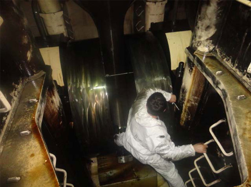
Crankshaft Inspection
Crankshaft should be frequently inspected to make sure that no cracks have been developed. It should never be secured or lifted without proper support along its length as its rigidity is mainly due to the support of the main bearings in the bedplates of the engine.
Crankshaft should be checked for cracks giving special attention to the points mentioned below:
- Working surface of journals and pins to be examined for signs of corrosion or pitting caused by water or acid contamination of the lubricating oil
- Shrink-fit reference marks should be checked
- Crank web deflection to be taken
- Tightness of coupling bolts should be checked
- Locking of coupling bolts to be examined
- Tightness of oil pipes and bearing locking devices should be checked
- Oil holes must be cleaned
- Balance weights securing arrangement to be checked and inspection for cracks to be carried out
- Plug in oil holes and check oil tightness
- Check crankpin bearing and main bearing clearances
Crankshaft Deflection
Crankshaft deflection is an important methods to check the condition of the main bearing and alignment of the crankshaft.
The crankshaft deflection results will also highlight the condition of the following:
- Wear down in the lower half of the main bearing or its saddle
- Structural hull deformation in and around engine room area due to imporper loading, ballasting and grounding
- Slackness in main engine foundation bolts, wear down of chalks, or shifted bedplate
Before taking the crankshaft deflection, following things to be kept in mind:
- As the readings taken are compared with original (initial) readings, ensure that the vessel is in light-ship condition
- Stop main enginen lube oil pump
- Do not take crankshaft reading if the vessel is out of water (Dry dock)
- Do not carry out crankshaft deflection if any of the running gear is removed for maintenance
- Ensure that the outside sea and wind conditions are calm
- Ship is at zero list or trim
- Reading must not be taken if the cargo operation is going on
- Before rotating the crankshaft for reading by turning gear, ensure that the indicating cocks are in open position
- Rotate the crankshaft via turning gear in the working direction of the engine
- Ease the pressure in the turning gear assembly by slightly pressing the ‘reverse turn’ direction button in the turning gear remote
- Ensure tie rod bolts are correctly tightened
- If the vessel is at tropical area with sunshine (high temperature) on one side of the vessel, taking measurement should be avoided as thermal deformation of hull and structure will affect the readings
- All holding down bolts should be in proper tight condition
- Immobalisation certificate must be taken from port and crankcase should be properly ventilated before entry
Crankshaft Deflection Procedure:
- When taking crankshaft deflection, keep the deflection gauge over the engine for sometime so that it adjusts to the surrouding temperature of the main engine.
- The crank web of each unit is provided with a punch mark where the deflection gauge is to be set for measurement. Clean the oil from the web and place the gauge in the marks. For additional precaution, tie the gauge with a thin rope to avoid it from falling into the sump.
- Turn the engine to BDC and then set the guage to “0” with slight pre-tension
Now turn the crank shaft in the ahead direction with the help of turning gear (check the maker’s recommendation as some manufaturers/ manuals will ask to turn engine to astern for CS deflection reading) and stop at the following points to take the deflection gauge readings:
Starting Pointj -Just After BDC(Gauge set at reading “0”)
Note this reading as “BDC1” reading.
90 Deg. Before TDC

Check the reading in the dial gauge and note it down as “Starboard” reading
At TDC

Check the reading in the dial gauge at this position and note it down as “TDC” reading
90 Deg. After TDC

Note down the dial gauge reading as “Port” reading.
Just Before BDC

Note down this reading as “BDC 2”
The two readings taken either side of BDC i.e reading “BDC1 and “BDC2” are averaged to get the BDC reading.
The deflection gauge reading should be recorded in the gauging sheet (provided with the ebook).
- TDC - BDC readings give vertical deflection, and
- Port - Starboard readings give horizontal deflection of the crankshaft.
The recorded readings are then interpreted in a graph and compared to the original graph to point out the wornout or defective bearings which are causing crankshaft misalignment.
Last unit reading might be higher due to overhanging of the flywheel
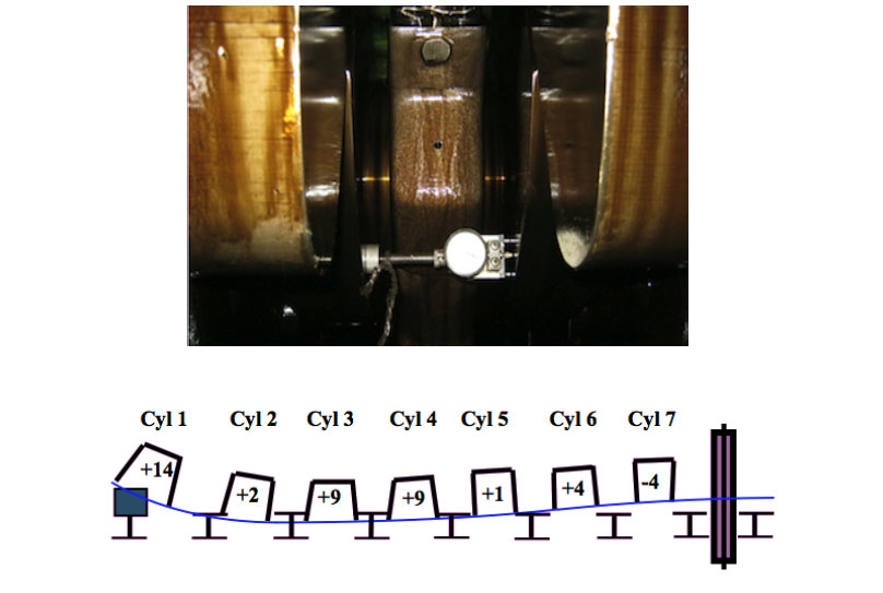
Crankshaft Deflection Curve
Curve Plotting:
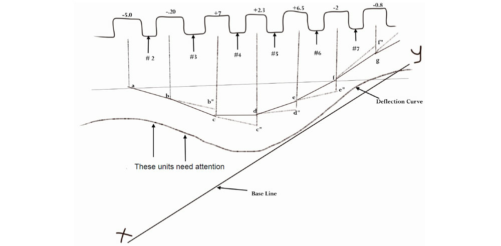
A straight line is drawn parallel to crankshaft and then perpendicular lines from each unit are drawn towards this parallel line.
The values derived after taking the crankshaft deflection of each unit is noted above every unit of crank web in the above graph.
Plot the distance -5.0 mm, which is the first deflection reading, downwards (downwards for negative value and upwards for positive value) from the reference line on the center line of unit and make the line “ab” which is at an angle proportional to the deflection at ‘a’.
This line is extended to intersect the center line of the next unit. The next step is to measure the deflection from this point of intersection and join the point from the previous point, which gives rise to the line “bc”. This step is repeated till the last unit.
Plot a smooth curve between these points and compare the position of this curve with respect to the base line XY. In the above graph, the curve drawn from the readings of bearings of unit 1 and 2 is are too far away from the base line as compared to rest of the curve and hence need attention.