Automatic Operation of Boiler
A marine boiler is commissioned with several automation systems so as to generate the required steam pressure with independent automatic operation. The automation includes monitoring and alarm systems, automatic feed supply system, level control system, fuel control system, electrical system and sequence operation system.
The boiler local control panel is provided with a selector knob to choose between 3 modes of the operation– “Auto”, “Manual” and “Stop”. In some ships, instead of operating from control panel, computerized operating program is designed to operate the boiler.
When not in use, the knob is selected to stop position, which de-energizes all electrical power to the boiler. Feed water pump and fuel pump has a separate power switch which needs to be operated in stop position if there is no requirement of fuel and water.
Automatic operation:
When the selector knob is positioned to “Auto”, considering the fuel pump system, pilot burner diesel oil pump and feed water system are already running in auto, following steps will occur:
- Once the auto operation is selected, the panel will send a signal to the starter of FD fan to operate. The forced draught (FD) fan will start for a set period of time controlled by the timer switch. Normally 3 to 4 minutes of time is allotted pre purging
- After the pre purging operation, power is supplied to the electrodes of pilot burner
- The solenoid valve installed in the line of pilot burner fuel line is energized and opened to allow the flow of fuel
- Fuel is supplied in the combustion chamber via pilot burner with electrodes creating spark
- Air is supplied in a controlled way through the air register in the furnace
- In the presence of heat source (spark), oxygen and fuel- flame is created inside the furnace
- The flame eye which is located in the furnace detects the pilot flame and sends a signal to the boiler control panel
- If there is a problem in pilot burner flame, the flame eye will not detect any flame which will trip the boiler
- If the eye detects flame, after a set period of time it sends a signal to the control panel, which then energizes the main burner fuel line solenoid valve and opens it
- Fuel is supplied to the main burner, which generates the flame in the presence of pilot flame and air registers
- A timer is installed and set to switch off the pilot burner after a period of time once the burner solenoid valve is open
- Flame eye is continuously monitoring the flame condition inside the boiler and if it does not detect any flame, a trip signal is send to boiler control panel
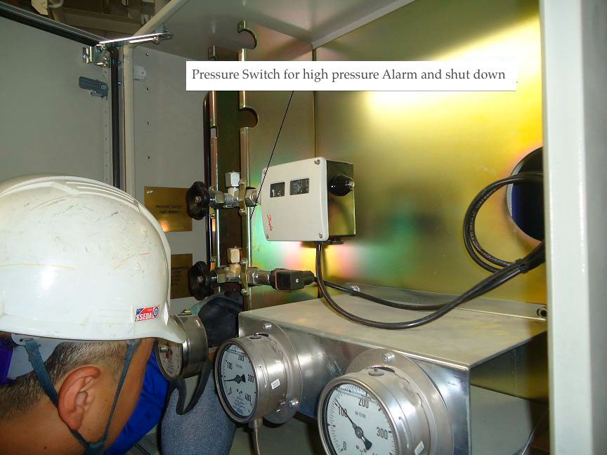
- A pressure transmitter is also installed with minimum and maximum pressure settings
- Once the maximum set pressure is reached, it sends a signal to the boiler control panel for stopping the main burner
- Since the boiler main burner is now off, due to the steam consumption the boiler pressure will reduce and once the minimum set pressure in the pressure transmitter is reached, it will give a signal to the control panel to start the overall operation again
Water Level Control System
The water is supplied to the boiler water drum through feed water pump. For an automatic operation, the feed water pump must know when to start and when to stop. If the feed pump runs continuously it may overflow the boiler which can cause priming or if the pump does not cope up with the demand, the water level will reduce below the required, leading to severe thermal stresses and overheating of the boiler. The feed water system is provided with a level control system, which commands the start and stop of the feed water pump to maintain the boiler water level. In a marine boiler, the following water level control systems are prominently used:
Level control float/ probe: This type of system is fitted either on the top of the boiler drum or in a water chamber attached to the boiler drum, which shows the actual water level as of the drum. In probe type system, a metal rod is suspended in the boiler water drum with electrical voltage along with an ammeter included in the circuit.
With the probe immersed in the water, current will flow through the circuit. If the probe is lifted out of the water, current will not flow through the circuit. The probe can be used to control starting and stopping of the feed water pump or to open the feed water valve integrated with level alarm (depending on the design of the system).
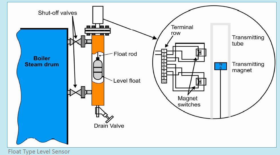
In a float type system, a float is suspended over the water and moves up or down as per the actual boiler level. The float is connected to a metal rod fitted with magnetic switches for starting or stopping the pump or opening and closing of the feed valve.
Alarms can also be integrated in this system by adding more magnetic switches in the desired level. Both float and probe type water level devices may give erratic readings in the presence of foam or oil in the boiler water.
Checks and Maintenance:
- Check all the electrical connections are tight
- If level indication is wrong and erratic, check for foam or oil in the boiler drum
- Regularly scum blow down the floating impurities
- For oil in water, boiler to be stopped and oil to be removed
- Check the working of the system on weekly basis for alarms and trips
- When boiler is de-pressurized, open the steel cap and clean the probes/float from salt deposits
- Ensure all the magnetic switches are working properly
- Check there is no damage to the float. Once it is pulled out, water pouring from the float indicates leakage
Differential pressure transmitter level switch: The DP transmitter level switch is mostly used in boilers of high-pressure capacity and where high quality input water is used.
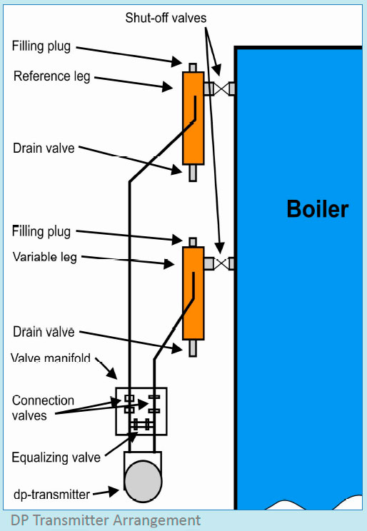
As the name suggests, it measures the difference in the pressures of two cells namely- Constant leg and Variable leg.
The constant or reference cell/leg is connected to the boiler drum above the highest water level and is filled with water during normal operation. Variable leg is connected at the lower point of the water level in the boiler drum.
Реклама внутри статьи
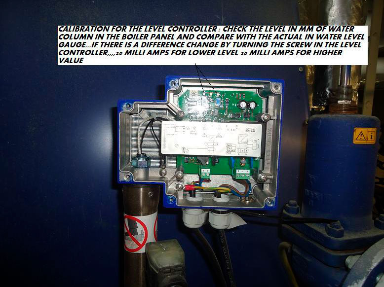
The differential pressure signal is normally elevated, electrically or pneumatically, so the output signal corresponds to the level in the boiler. 0% of water in the level glass corresponds to 4 mA (3 psi) and 100% corresponds to 15psi or 20 mA. The major advantage of DP water level measuring system is that it is insensitive to foam as this method is based on weight of water in the drum.
Maintenance: There are three important maintenance procedures related to DP transmitter level controller:
Blow down of variable and reference legs: The blow down procedure to be carried out at least once in a month and its frequency should be increased in case the water is contaminated with mud, salt, sludge etc.
The blow-down procedure should be performed as describe below when the boiler plant is in operation and in steady load condition. When the blow-down procedure is carried out, it is very important that the water level in the boiler is carefully and continuously supervised by the ship engineer. The feed water control valve must be operated manually, if necessary.
Procedure for blow down:
- Isolate the differential pressure transmitter by closing the two transmitter connection valves in the manifold
- The equalising valve must remain closed during the blow-through procedure and normal operation
- Open the drain valves provided in the impulse legs slowly
- Allow the legs to blow-through for a few seconds
- Close the shut-off valve for the reference leg
- Close the drain valves once the reference leg is completely depressurised
- Fill the reference leg with feed water through filling plug
- Screw on the filling plug and slowly open the shut-off valve for the reference leg
- Open the two transmitter connection valves in the manifold
- After performing the blow-down check that the DP water level transmitter unit and feed water control valve are fully operational
Blow-through procedure of the connection pipes: The connection pipes in the DP transmitter system requires blow through to avoid clogging of the system. The blow through must be performed at least once in a year but its frequency should be increased in case the water is contaminated with mud, salt, sludge etc. The blow through to be carried out with boiler in stop position but still in pressurized condition. Follow the procedure below:
- Open the venting facilities for the impulse leg located on the valve manifold
- The transmitter connection valves must remain open and the equalising valve to be closed during the blow-through procedure
- Close the venting facilities on the valve manifold once clean water escapes
- Close the shut-off valve for the reference leg
- Slowly open the drain valve of the reference leg
- Close the drain valve again when the reference leg is completely depressurised
- Unscrew the filling plug of the reference leg and fill the leg with feed water
- Screw on the filling plug and slowly open the shut-off valve for the reference leg
In some marine boiler, both DP transmitter and level float system are simultaneously used. The DP transmitter is solely used for level control and float system is used to detect the level and activate alarms and trips.
Alarms and Shutdowns
Boiler alarms and trips are important part of automation, without which automatic operation of boiler is impossible. Engineers to ensure all the alarms and trips are functioning correctly at all times.
A marine boiler comprises of different alarms that give pre-warning for a subcondition, which if overlooked can lead to operational and maintenance problems.
Following is the list of the alarms integrated in the boiler system:
Low and high water level alarms: A level float switch supervises the water level in the boiler. It is installed in a vertical position and connected to the boiler sockets. A float and float rod carry a transmitting magnet, which runs in a stainless steel transmitting tube. The transmitting magnet operates the externally installed magnet switches when it comes in contact with the same, triggering an audio-visual alarm.
In place of float, conductivity probes can be used to detect water levels. For low and high water level, two different probes operating on the principle of resistance to earth will be installed.
Each probe electrode acts as a simple switch, indicating low resistance to earth if it is in contact with water, or high resistance if the probe is out of water.
Low boiler pressure alarm: A pressure transducer is fitted in the boiler, which is connected to audio-visual alarm system. When the boiler reaches a set point of low pressure, the alarm will be sounded.
High and low fuel oil temperature alarms: A temperature sensor is fitted in the fuel line of the boiler burner, which gives its output to alarm transducer for high and low temperature alarms.
Standby pump changeover alarm (when running pump trips): If due to any fault, the running pump is stopped and as a result stand by pump starts, it will give an alarm for stand by pump running. Check the cause for stoppage of the running pump.
Cascade tank high salinity alarm: The cascade tank is fitted with a salinometer which detects the salt content of the cascade tank. If the salinity is on the higher side and gives an alarm, check for seawater leakage in the system.
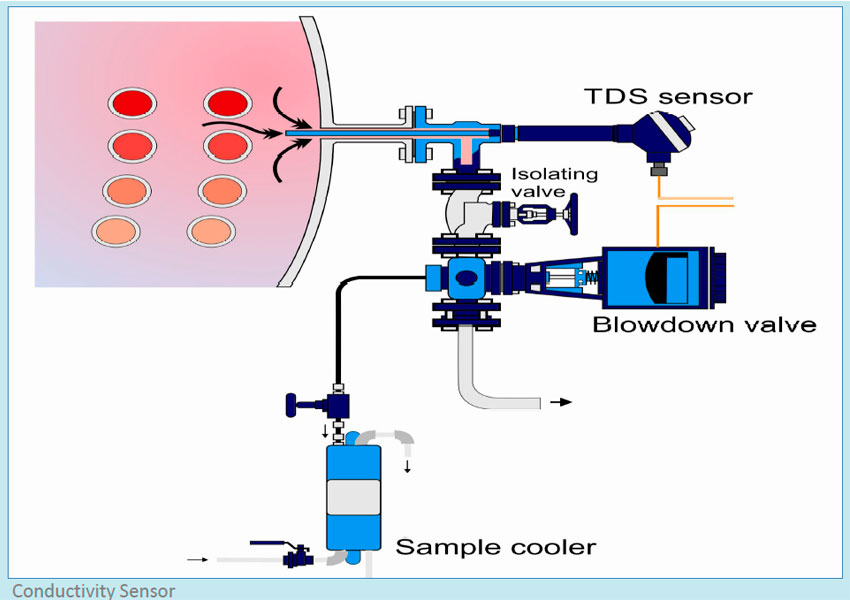
High conductivity: A conductivity sensor is also installed to check the content of total dissolved solids in the boiler water. Conductivity depends on both ion concentration and ion mobility. Mobility generally increases with temperature and conductivity measurements are temperature dependent, increasing about 2% for each °C increase in temperature.
Oil detection alarm: Cascade tank is also fitted with oil sensor in the hot well water. If oil is detected in the cascade tank, all means to be taken not to allow the oil to go inside the boiler. Check and troubleshoot the cause of oil in the boiler water immediately.
Boiler shutdown trips:
Boiler is provided with different shutdowns to protect it from thermal stresses, overheating, loss of steam pressure etc. Following are important trips and cutouts installed in a marine boiler:
Low low (L.L) level: Once the low level alarm is sounded and the water level is further reducing, the boiler will trip at a point which is below the low level alarm.
High high (H.H) level: The water level sensor also senses for high level. If the level controller is malfunctioning and water is continuously pumped inside the boiler, it will not only induce thermal stresses but also result in carry over. To avoid this, a high -high level trip is installed.
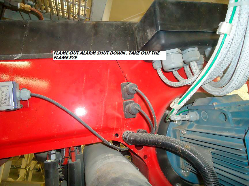
Flame failure: A photocell is fitted in the furnace, which continuously monitors the flame.
If due to any fault, the flame inside the boiler extinguishes, the photocell in the flame sensor will not detect any light and flame failure alarm will be sounded. This will protect the boiler from depressurizing.
High steam pressure: The boiler pressure is continuously monitored and if the pressure exceeds a set limit, the boiler will be tripped to avoid explosion (in case other safety system does not respond).
Low F.O temp: Low temperature trip is set further below the low temperature alarm. If the oil temperature drops even after low temperature alarm has been sounded, the boiler will trip to safeguard the burner equipment.
High F.O temp: The high temperature trip is set above the low temperature alarm. If the oil temperature rises even after high temperature alarm has been sounded, the boiler will trip to safeguard the burner equipment and to avoid penetration of fuel in the furnace.
F.D fan failure: The forced draught fan supplies purging and combustion air to the boiler furnace. If the F.D fan has not started at its time slot, the boiler automation will trip the boiler.
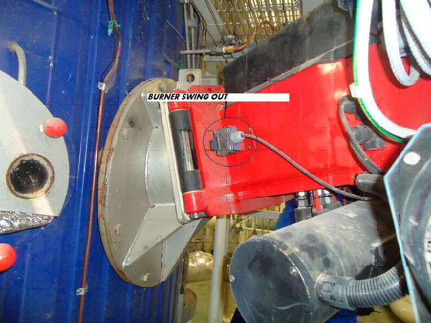
Burner door open: The boiler burner door is provided with an easy lock, which can be opened so that the door can be swung out for handy burner maintenance and checks.
A contactor switch is fitted in the boiler door and boiler shell which when not in contact, the boiler won’t be allowed to start.
Very high conductivity trip: It is very harmful to operate the boiler with high TDS (Total dissolved solid) as it will drastically reduce the heat transfer ability of the boiler. The TDS is monitored by continuously checking the conductivity of the boiler water. If the conductivity is crossing the normal limit, it will give an alarm and if it further rises, the boiler will trip.
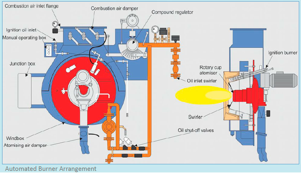
Boiler Burner Control Sequence
The boiler burner operation is automatically operated through sequence controller, which ensures not only efficient combustion but also safety of the boiler furnace by pre and post purging with forced draught air.
The automation in burner operation results in the best possible combustion provided the fuel used is of good quality and well treated. In comparison of manual operation, automation of Burner Systems will result in:
- 25-40% reduction in fuel costs
- Typical payback period of 2 - 4 years
- Reduced carbon emissions
Below is the procedure of boiler burner control sequence:
- Burner Ignition Sequence “ON”
- FD fan auto starts for post purging
- Fuel pump auto starts
- Furnace purging starts and atomizer steam valve to the burner opens
- Furnace purge finishes
- Checks for burner ignition- Furnace purge completion-F.O temp =110 °C – F.O recirculation valve shut – FO pressure at burner >10 bar – F.O pump running – Setting air fuel ratio
- Pilot ignition condition established to operate for 5 seconds
- Flame eye detects flame within 8 sec after pilot ignition
- Main burner ignition after 3 sec of pilot burner ignition check
- F.O valve to burner opens fully
- Pilot burner pump stops and valves shut
- If flame eye detects no flame, boiler trips
- Completion of burner sequence
- When burner stops, it is immediately purged with steam
Feed Water Supply Control System
Boiler feeding can normally take place in the following three ways:
- On/Off control
- Only through feed valve or in combination with variable speed
- Variable speed
1. On/off control:
In on/off control system, the feed pump is controlled by level sensor or a differential pressure transmitter, which is fitted in the boiler drum. When the water level falls below the “Pump On” level, the feed pump starts and runs till the water level rises to “Pump Off” level. This system is used for boiler with low steam quality requirement, as the pumping of large quantity of water at one go will reduce the steam quality.
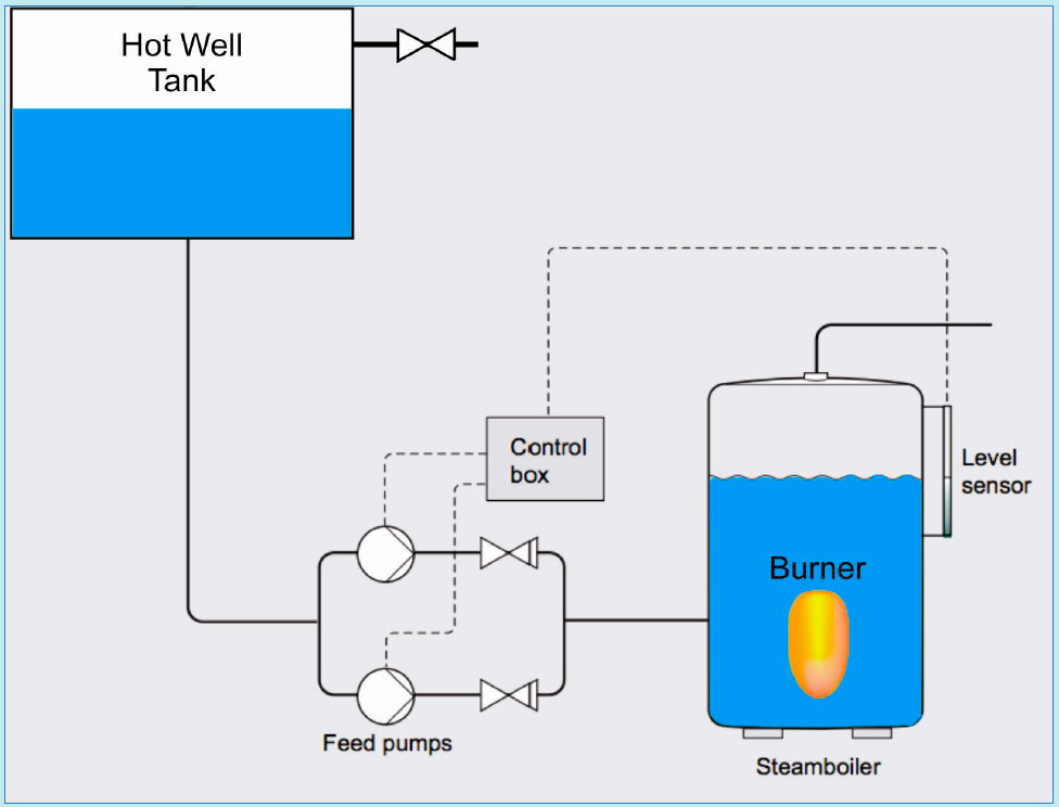
Advantages:
- Low and easy installation
- Low operating cost
- No bypass is installed
Disadvantages:
- Poor steam quality
- Variation in steam production
- Danger of carry over
2. Through feed valve control:
The water level in the boiler drum is controlled by the opening and closing of the feed valve. A level sensor or a differential pressure transmitter positioned on the boiler controls the operation of the feed valve. The feed valve is adjusted according to the steam consumption of the engine room. This however requires that the feed pump is set to continuous operation.
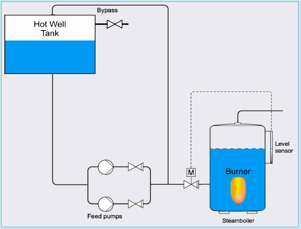
As this system operates smoothly, it is ideal for all types of steam boilers, both small and large, and it also minimizes the risk of over-boiling. Remember to size bypass valve according to the feed pumps minimum flow, which is 10 % of nominal flow for the pump. It may be good idea to stop the pump when the valve is closed, however this requires a signal from the valve.
Advantage:
- Boiler feeding adjusted according to `steam consumption’
- Higher efficiency than “on and off” control
Disadvantage:
- The pump must be set on continuous operation, which increases energy consumption
- Requirement of bypass
- The feed valve is expensive
- Pressure loss across the feed valve
3. Through variable feed pump:
As the name suggests, the feed pump with variable delivery is responsible to maintain the water level in the boiler.
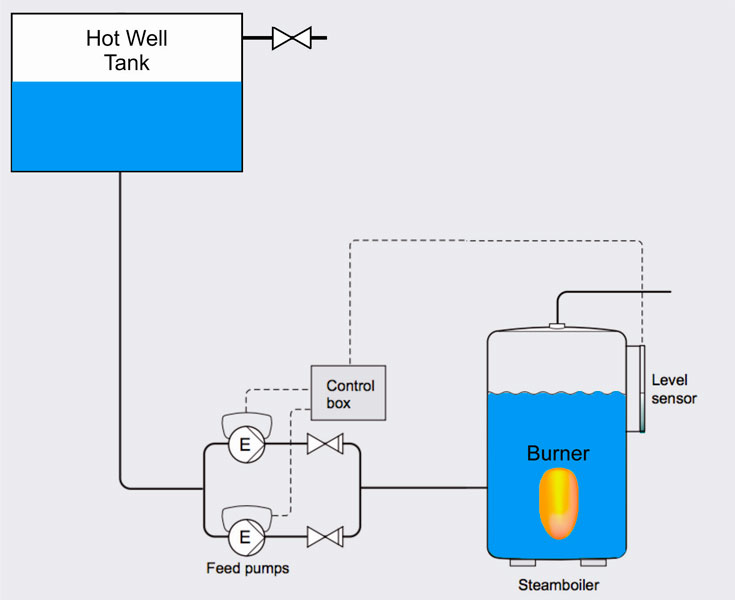
No control valve is fitted in the line and the signal received from level transmitters is taken as an input for supplying water in the drum. Hence, the water intake is controlled as per the steam demand. As this system operates smoothly, it is ideal for all types of steam boilers, both small and large, and it also minimizes the risk of over-boiling
Advantages:
- Boiler feed is as per the steam demand
- Better efficiency
- Energy saving on pump operation
- No pressure loss across the feed valve
- Less expensive in installation and operation than feed control valve system
Disadvantage:
- Precise setting of pump operation
References
A Guide to Boiler Operation and Maintenance. Anish Wankhede [2015]