Low pressure system
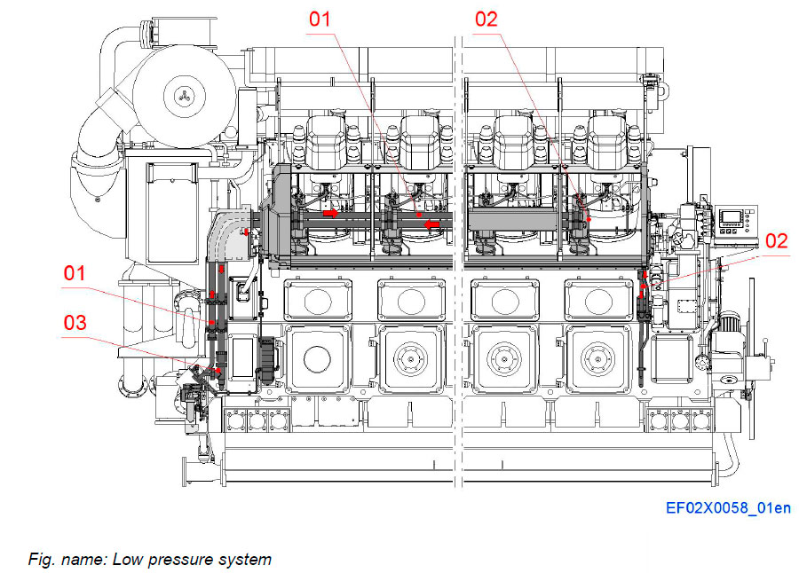
The low pressure fuel oil system on the engine consists of the fuel delivery piping and leak fuel system. The aim of the low pressure system is to transfer clean fuel oil to the injection pump and transport the fuel oil back to a tank for reuse.
The pressure level of the circulating system is kept correct and constant by the pressure regulating valve mounted on the engine.
System components
- 01 Main fuel delivery piping
- 02 Leak fuel system
- 03 Pressure regulating valve
FUEL SUPPLY LINE FROM A-BANK TO B-BANK

System components
- 01 Main fuel delivery piping
- 02 Main fuel return piping
- 03 Distributing piece
Pipe connections
- A Supply line
- B Return line
A-BANK

System components
- 01 Main fuel pipe
- 02 Fuel distribution housing
- 03 End flange
- 04 Support ring
- 05 Square ring
- 06 Guide ring
- 07 O-ring
Pipe connections
- A Supply line
- B Return line
B-BANK

System components
- 01 Main fuel pipe
- 02 Fuel distribution housing
- 03 End flange
- 04 Support ring
- 05 Square ring
- 06 Guide ring
- 07 O-ring
Pipe connections
- A Supply line
- B Return line
Leak fuel system
A-SIDE

At the A-side leak fuel system consist of piping in the Hot-box, leak oil channels in the aluminium manifold and end covers in the side cover lower part and leakage piping at driving end of the engine.
System components
- 01 103 Clean main fuel leakage
- 02 104 Dirty main fuel leakage
- 03 Fuel leakage from injection pump
- 04 Fuel leakage from high pressure pipe
- 05 Leakage oil from injection valve
B-SIDE

At the B-side leak fuel system consist of piping in the Hot-box, leak oil channels in the aluminium manifold and end covers in the side cover lower part and leakage piping at driving end of the engine.
System components
- 01 103 Clean main fuel leakage
- 02 104 Dirty main fuel leakage
- 03 Fuel leakage from injection pump
- 04 Fuel leakage from high pressure pipe
- 05 Leakage oil from injection valve
- 06 Pilot fuel leak alarm
HOT-BOX, A-BANK

Leak fuel from the injection system is collected in a leak fuel manifold on the Hot-box. The manifold is divided in two sections to collect the leakage. One is for leakage from pumps and the other is for leakage from the high pressure pipes. Leakage from injection valve is collected to pilot fuel return line.
This fuel is collected and drained through the same leak pipes situated at driving end or both ends of the engine, to the clean fuel leak tank for reuse. A level switch on the leak fuel outlet pipe monitors the leakage and will initiate an alarm from an abnormally high backflow or from a leak in an injection pipe. Leak fuel, lubricating oil and water is collected to a separate leak pipe system situated at driving end or both ends of the engine and is returned to a separate waste fuel oil collection tank.
Connections
- A 103 Clean main fuel leakage
- B 104 Dirty main fuel leakage
- C Fuel leakage from injection pump
- D Fuel leakage from high pressure pipe
- F Leakage oil from injection valve
- G Pilot fuel return
HOT-BOX, B-BANK

Leak fuel from the injection system is collected in a leak fuel manifold on the Hot-box. The manifold is divided in two sections to collect the leakage. One is for leakage from pumps and the other is for leakage from the high pressure pipes. Leakage from injection valve is collected to pilot fuel return line.
This fuel is collected and drained through the same leak pipes situated at driving end or both ends of the engine, to the clean fuel leak tank for reuse. A level switch on the leak fuel outlet pipe monitors the leakage and will initiate an alarm from an abnormally high backflow or from a leak in an injection pipe. Leak fuel, lubricating oil and water is collected to a separate leak pipe system situated at driving end or both ends of the engine and is returned to a separate waste fuel oil collection tank.
Connections
- A 103 Clean main fuel leakage
- B 104 Dirty main fuel leakage
- C Fuel leakage from injection pump
- D Fuel leakage from high pressure pipe
- E Pilot fuel leak alarm
- F Leakage oil from injection valve
HOT-BOX

Connections
- A 103 Clean main fuel leakage
- C Fuel leakage from injection pump
- D Fuel leakage from high pressure pipe
- F Leakage oil from injection valve
Pilot fuel system on engine

The pilot fuel system is a common rail system fed by gear wheel driven pilot fuel injection pump at the end of the engine.
A connection piece is mounted to each cylinder head connecting the one per cylinder rail pipes. From the connection piece the fuel is fed through a connection pipe to the injection valve.
The injection valve is a two-needle type combined pilot and main diesel fuel injection valve, where the pilot injection is electronically controlled.
Pilot fuel is filtered by duplex filter before pilot fuel pump and water separated in fuel return circuit.
System components
- 01 Pilot fuel system at free end
- 02 Pilot fuel common rail piping, (A- and B-sides)
- 03 Water separator
- 04 Pilot fuel filter
Pipe connections
- A 112 Pilot fuel inlet
- B 117 Pilot fuel outlet
Pilot fuel system at free end

System components
- 01 Pilot injection pump
- 02 Safety valve for pilot fuel
- 03 Fuel filter
- 04 Water separator
Pipe connections
- A 112 Pilot fuel inlet
- B 117 Pilot fuel outlet
- C Pilot fuel return
- D Pilot fuel delivery
- E Drain from pump
- G Drain from safety valve
System components
- 02 Safety valve for pilot fuel
- 05 Connection piece

Pipe connections
- A 112 Pilot fuel inlet
- B 117 Pilot fuel outlet
- C Pilot fuel return
- D Pilot fuel delivery
- G Drain from safety valve
Pilot fuel common rail piping

HOT-BOX, A-BANK
The pilot fuel common rail piping consists of double wall piping at free end side and Hot-box. Piping is equipped with leak alarm pipes.
Pilot fuel common rail pipes are connected with metallic sealing cone into connection pieces.
The double wall injection pipes are delivered complete with connection nuts assembled.
Components
- 07 Pilot fuel connection piece
- 08 Pilot fuel common rail pipe
- 09 Leak alarm pipe
- 11 Pilot fuel leakage pipe
- 12 Connection piece
Pipe connections
- C Pilot fuel return
- D Pilot fuel inlet
HOT-BOX, B-BANK

The pilot fuel common rail piping consists of double wall piping at free end side and Hot-box. Piping is equipped with leak alarm pipes.
Pilot fuel common rail pipes are connected with metallic sealing cone into connection pieces.
The double wall injection pipes are delivered complete with connection nuts assembled.
Components
- 07 Pilot fuel connection piece
- 08 Pilot fuel common rail pipe
- 09 Leak alarm pipe
- 11 Pilot fuel leakage pipe
- 12 Connection piece
Pipe connections
- C Pilot fuel return
- D Pilot fuel inlet
- E Pilot fuel alarm leakage
HOT-BOX, FROM A-BANK TO B-BANK

Components
- 08 Pilot fuel common rail pipe
- 09 Leak alarm pipe
- 11 Pilot fuel leakage pipe
Pipe connections
- C Pilot fuel return
- D Pilot fuel inlet
- E Pilot fuel alarm leakage
Pilot fuel injection pump

The pilot fuel pump is an 8- or 4-cylinder radial piston pump directly driven by the pump gear at the free end of the crankshaft. The built-in pressure regulating unit is electrically controlled by the engine control system. On the feed line a valve group with a filter regulates the inlet pressure to the pump. A safety valve is mounted on the high pressure line.
The pump shaft is equipped with two roller bearings. The pump elements slide on ceramic slide rings, one ring per two elements. The fuel oil functions as lubricating media. The pump is equipped with an indication hole for shaft sealing leakage.
- 4 cylinder pump for L-engine
- 8 cylinder pump for V-engine
Pilot fuel injection pump

Components
- 01 Sliding ring
- 02 Distance plate
- 05 Throttle valve
- 06 Spring
- 07 Control piston
- 08 Solenoid
- 09 Shaft lubricating bush
- 10 Distance piece
- 11 Roller bearing
- 12 Shaft sealing
- 13 Flange screw
- 14 Roller bearing
- 17 Flange screw
- 18 Connector
- 19 Connecting piece
- 20 Fastening ring
- 21 Blocking plug
- 22 Connecting nut
- 23 Filter
- 24 Leak detection
Pipe connections
- A Supply connection
- D High pressure connection
- E Drain connection
- P1 Lubricating fuel supply
- P2 High pressure accumulator
Pilot fuel injection pump

- 03 Piston guide
- 04 Piston
- 15 Inlet valve
- 16 Pressure valve
- 17 Piston spring
- 18 Pump housing
Pipe connections
- A Fuel feed line
- B Fuel high pressure line
Function
- 1. Fuel suction phase
- 2. Fuel pressurising phase
Drive gear for pilot fuel injection pump

The pilot fuel injection pump is driven by drive gear wheel at the end of crankshaft, which rotates pump mechanism. Gear wheel of pump is mounted by means of friction connection.
Pump is positioned correctly into pump cover with flange of pump and fastened by screws.
Components
- 01 Gear wheel
- 02 Driving gear wheel
- 03 Screw
- 04 Stud
- 05 Nut
- 06 Sealing ring
- 08 Hub for gear wheel
Pilot Injection line

The pilot fuel injection line consists of two parts, connection piece and connection flange. Connection piece is connected into the side of the nozzle holder with conical connection and seals with plain metallic surfaces. Pilot fuel common rail pipes are connected with metallic sealing cone.
Components
- 07 Pilot fuel connection piece
- 12 Connection flange
Pipe connections
- B Fuel leakage, injection valve
Pilot Injection line

Components
- 07 Pilot fuel connection piece
- 08 Pilot fuel common rail pipe
- 09 Leak alarm pipe
- 10 O-ring
- 11 Tightening screw
- 12 Connection flange
Литература
www.wartsila.com