The fuel pumps of a 2 stroke marine engine are high pressure supply pumps that control the quantity and timing of fuel injected in the combusion chamber. The most common types of fuel pumps used on 2 stroke engines are:
Suction-spill valve control pump:
This pump is popularly used in SULZER engines. In this type of pump, the closing of suction valve ensures delivery of fuel and opening of spill valve indicates end of the delivery.
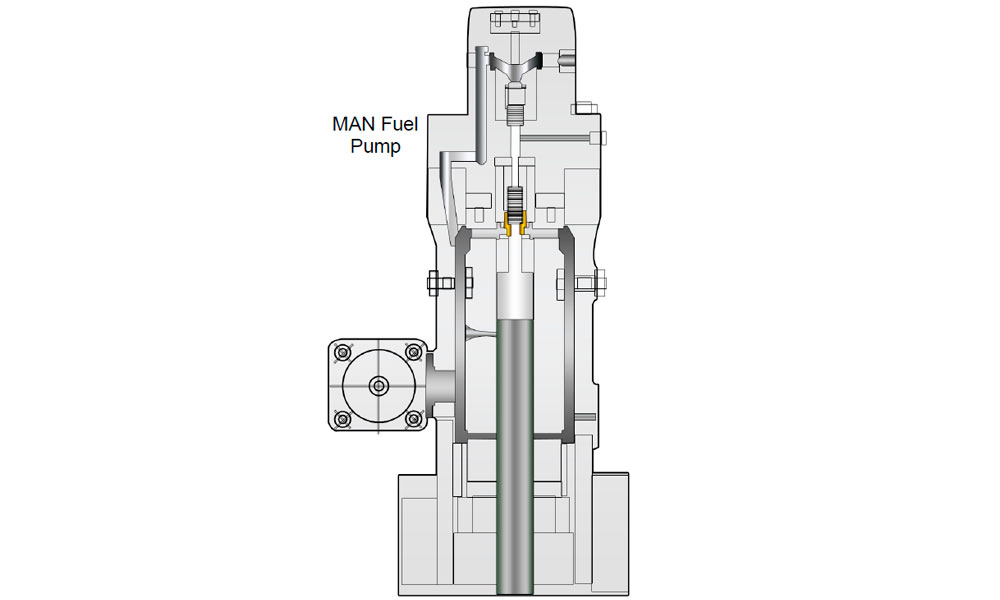
Jerk type helix type port control pump:
This pump is used by MAN engines where the helix groove in the plunger port decides the end of injection and closing of the suction port by the plunjer indicates delivery of high pressure fuel.
The most important thing which is checked in the fuel pump is the timing. “Timing” here describes the point at which the pump will deliver the fuel to the fuel valve.
If the timing is not correct, then there may be inefficient combustion or over pressurisation inside the cylinder.
As described above, due to two different types of pumps, we use two different methods to check the delivery stroke of the fuel pump i.e effective stroke of the fuel pump.
Suction spill control valve type fuel pump Timing Check:
Before opening the fuel pump for checking the timing, ensure to change over the engine from heavy oil to diesel oil and take prior permission from the company and port authority for immmobilisation. Procedure for checking fuel pump timing:
- Keep the main and crosshead lube oil pumps running
- Put local reversing lever in ahead direction
- Shut starting air valve to main engine and inlet air valve to distributor
- Open indicator cocks and engage the turning gear
- Now put the local fuel lever to the max fuel notch position. This will vent the cylinder in the governor and also activate the shut down servomotor i.e. rack is free to move from ‘0’ to ‘maximum’ position( Once the engine is stopped, the shut-down servomotor gets de-activated i.e. air vented and it keeps the fuel rack locked in the zero postion).
- Measure the VIT rack distance and note it down. Set it to zero and lock it with spacer and nut
- Fuel quality lever to be set at ‘0’
- Keep three dial gauges near the engine
- Shut the fuel inlet to the pump and drain the oil from the pump casing by opening the bottom drain valve
- Remove the protection cover from the suction, spill and discharge valve
- Remove pressure bush with special tools ( the pressure bush holds the valve seat in place)
- Remove the springs and valves
- Clean the valves and springs with kerosene
- Mount back the spill and suction valves and pressure bush without springs
- Turn the engine in ahead direction till the cam is on its peak. This ensures that the suction valve is closed
- Keep the dial gauge over top of the suction valve with 1mm pre-tension and set it to ‘0’
- Now turn the engine in astern direction till the cam is on the base circle, which indicates spill valve is closed
- Put dial gauge over top of the spill valve with 1mm pre-tension and set it to ‘0’
- Keep the third dial gauge over the plunger of discharge side with 1mm pretension and set it to ‘0’
- Now turn the engine in ahead direction till the dial gauge on suction valve shows 0.02 mm deflection. Check and note the reading of plunger dial gauge and mark it as ‘a’
- Keep turning the engine till the dial gauge on the spill valve shows 0.02mm deflection. Note the reading
- of plunger dial gauge and mark it as ‘b’
- Effective stroke of the fuel pump= ‘b’ – ‘a’
Jerk type/ Helix Port Controlled Pump:
In jerk type helix port controlled fuel pump, the timing is measured by taking the fuel pump lead.
The fuel pump lead is the distance from the top of fuel pump plunger when lifted above the upper edge of the upper cutoff holes of the fuel pump barrel,when the same unit’s piston is at TDC.
Following procedure is to be used for finding out fuel pump lead:
- Close the oil inlet to the fuel oil pump and drain the pump
- Disconnect the fuel oil index rod from the fuel rack
- Open the erosion plugs from the fuel pump housing
- Diconnect the high-pressure pipes and air pipe for the puncture valve
- Remove the puncture valve from the top cover
- Use the extractor tool to remove the suction valve from the top cover
- Use compressed air to clean the lower cut-off holes and the cross bore
- If the engine is of the reversible type ensure that the roller guide is in AHEAD position
- Turn AHEAD until the cross bore in the plunger is aligned with the lower cutoff holes
- Ensure that the plunger is in delivery stroke to obtain the correct alignment of plunger and cut off holes
- Push the measuring pin right down against the bottom of the hole in the plunger
- Verify that the cross bore and the lower cut-off holes are in alignment by flashing a torch through the cut-off holes
- Turn AHEAD until the lower edge of the cross bore in the plunger reaches the exact position at which it closes off the upper edge of the lower cut-off holes
- If the exact position is difficult to determine due to fuel oil deposits in the plunger/barrel assembly, use compressed air to clean the lower cut-off holes
- Now mount the measuring tool on top of the fuel pump cover
- Adjust the bracket of the measuring tool until the plunger of the dial gauge is almost at its bottom position. Adjust the scale to 0 (zero)
- Turn AHEAD until the piston of the cylinder concerned is at TDC
- When the exact position of the piston has been confirmed to be at TDC, either by checking the position of the crankthrow or the marks on the turning wheel, note down the reading on the dial gauge and calculate the deviation “x” between the “0” position and the present position
The fuel pump lead “a” is then calculated as follows: “a = x + Y (correction factor)” The adjustment factor “Y” is a correction factor. It is basically the distance between the plunger top and upper cutoff holes top, when the plunger top reaches the exact position at which the light cannot be seen through the lower cut off holes in the barrel and plunger.