MAIN BEARING
The rotational power of a ship’s propeller is determined by the power produced by the marine engine to rotate the crankshaft.
The crankshaft of the main engine is supported and connected to the connecting rod via main bearings whose main function is to transmit the load without any metal-to-metal contact.
This is achieved by choosing special materials for manufacturing main bearings, which floats the journal pin of the rotating crankshaft when lube oil is supplied to it.
Properties of main bearing materials:
- It must be anti-friction type
- It must be of anti-corrosive type
- Good running in and grinding in ability
- Good load carrying capacity
- Good embeddability property
- Must support the oil film
- Good tensile and compressive strength
- Must not react with the lube oil
- It must have thermal resistant property to avoid any damage in case it’s running hot
Types of Main Bearing
Three famous types of main bearings used for propulsion 2 stroke engines are as follows:
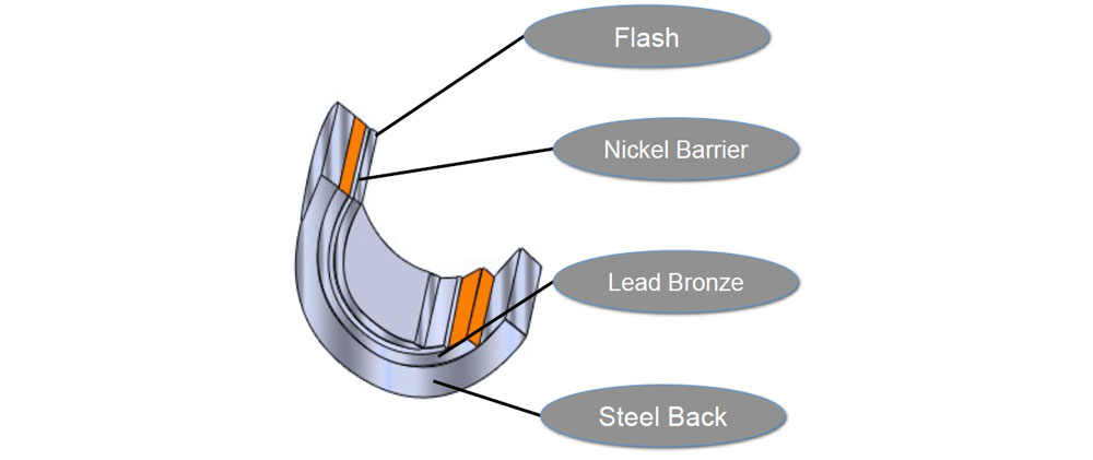
Lead Bronze Bearing: These bearings consist of the following layers
- Flash layer: It is the top most layer with thickness of 0.035mm and made up of tin and lead. It is used to protect the bearing from corrosion and dust when not in use. This layer flashes off when bearing is under running-in.
- Nickel Barrier: It is the second layer made up of nickel with thickness of 0.02mm. Its main function is to prevent corrosion and avoid diffusion of tin into bearing metal.
- Lead Bronze: The third layer composed of lead bronze has excellent anti seizing property and is the principle component, which acts as the bearing.
- Steel back: Steel back is the last and backing part of the bearing used for shape and support, over which all the layers are bonded together.
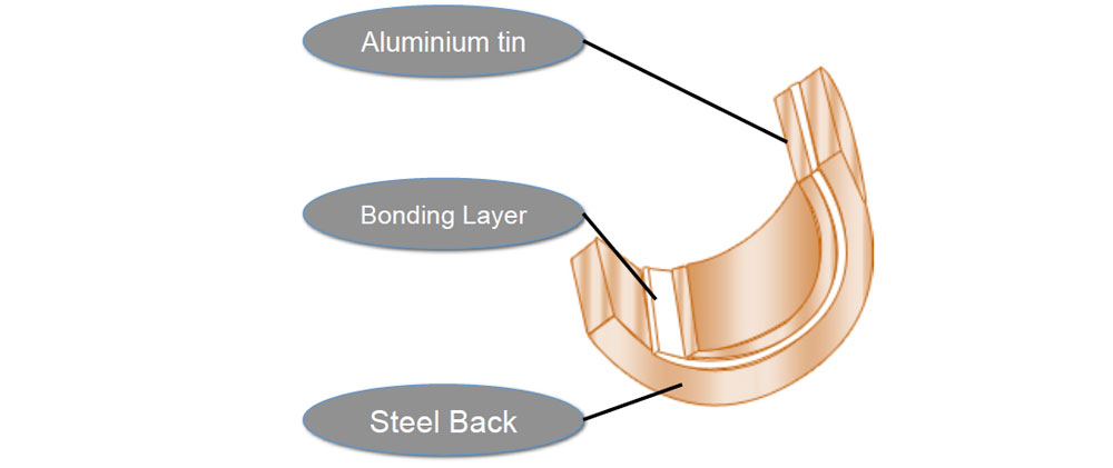
Bi-metal Bearing: This bearing consists of following layers
- Aluminium Tin: The first layer of bimetal consists of Al and Sn with thickness of 0.5 to 1.3 mm. It is the main layer of this type of bearings.
- Bonding Layer: The bonding layer is made of aluminum and has 0.1mm thickness. The main function of the bonding layer is to obtain a good bond between the shell and the top layer.
- Steel Back: The steel back part is used for shape and support.
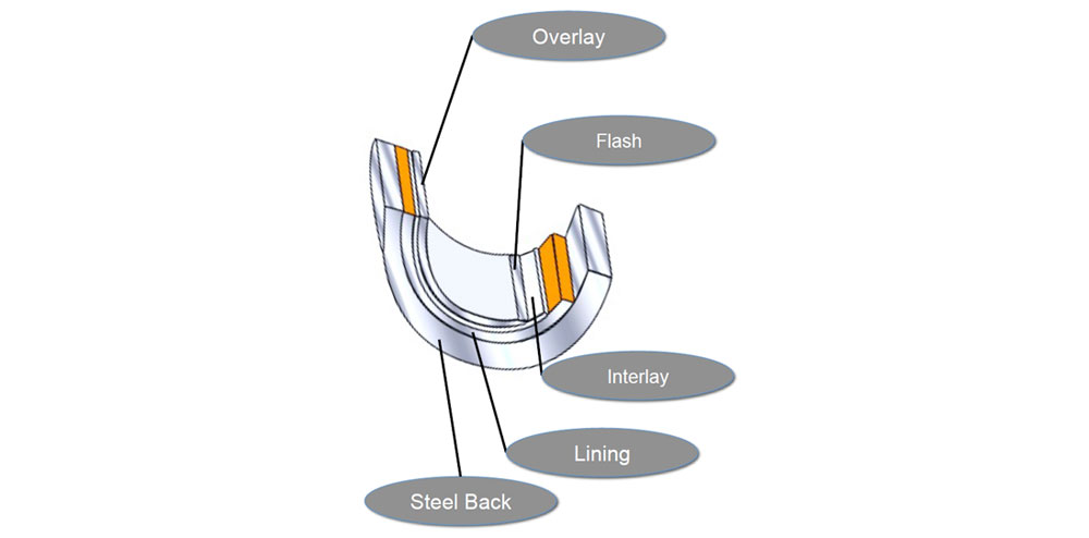
Tri Metal Bearing: These bearings are called tri metal bearing because they consist of three main layers (excluding flash layer as it flashes off) and a steel back. It consists of:
- Flash Layer: It is the top most layer with thickness of 1 micron and is made up of tin and lead. It is used to protect the bearing from corrosion and dust when not in use. This layer flashes off when bearing is in runningin period.
- Overlay: The second layer is made up of white metal, (Tin Antimony Copper) which is the main component in this type of bearing. Its thickness is 20 microns.
- Interlay: It is the third layer used as anti corrosive layer for overlay. It is of 5 microns thickness.
- Lining: It is the lining layer between interlay and steel back with thickness of 1 mm and is made up of lead and bronze.
- Steel Back: The backing part used for shape and support.
Measuring Main Bearing Clearance:
A marine engine comprises of several types of bearings, which support the rotating and reciprocating crankshaft, camshaft, and crosshead of the engine.
It is extremely important to maintain good quality and quantity of lubricating oil to all these bearings in order to avoid breakdown of the engine.
The main bearing of a marine engine supports the long running crankshaft throughout the engine length. This makes it imperative to check the condition of the bearing at regular intervals of time.
The clearance measurement of the main bearing determines the amount of wear down, which the bearing has been subjected to. There are various types of methods adopted by different marine engine manufacturers to measure the clearances of the main bearing of marine engine. Following are some of the most prominent methods used onboard ships to measure the clearance of main bearing:
1) Bridge with Depth Gauge
This method is used in SULZER 2 stroke marine engines where the bearing‘s shell is removed along with the keep (the bearing shell is lined with the keep). After that a bridge is fitted over the top of the journal pin, from port to starboard, making a bridge over the crankshaft with two ends supported on the cross girder.
A simple vernier type depth gauge is then inserted in the hole provided on the bridge and the scale of depth gauge is rested on the crankshaft pin. The total depth on the scale is measured and compared with the previous reading and the reading in the manual for calculating the wear down of the bearing.
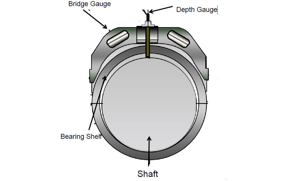
In old model SULZER engines, a collar is provided in the bearing shell along with a small hole. Thus, without removing the keep, the bridge is fitted adjacent to the keep and the depth gauge is used from the hole provided in the shell to measure the shell wear down.
2) Bridge With Feeler Gauge: In some engines, after removing the shell and the keep, the bridge is installed as explained in the above point.
Also, in place of depth gauge, a feeler gauge is used to measure the clearance between the journal pin top and the bridge bottom.
The bridge used here is different in terms of height and the gap between pin and the bridge is very less compared to that of the bridge used in the earlier method.
3) Telescopic or Swedish Feeler Gauge
In engines like MAN B&W, this is the most common method used to measure the bearing clearance of the top shell. In this method there is no need to remove any connection or bearing keep for measuring the clearance.
The telescopic gauge is inserted between the gap of the crank web and the bearing keep.
When the tip reaches the shell top, the feeler is inserted between the shell and the pin to check the clearance
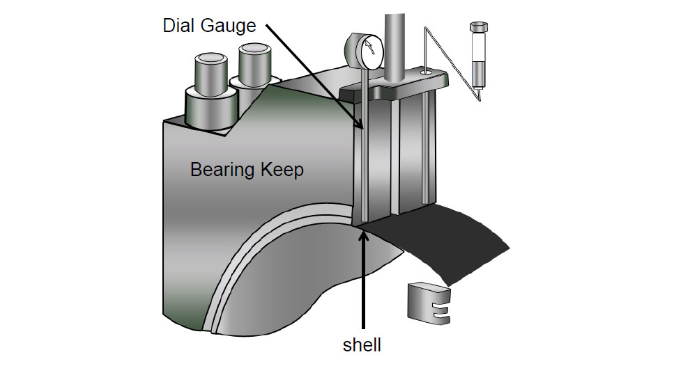
4) Dial type Depth Gauge: This method is used in new MAN B&W engines (SMCC), which does not require the top keep to be removed.
The lube oil pipe connection screw hole is in the bearing keep, which can be accessed from the hole on the bearing shell.
The dial gauge is inserted in this screw hole and the reading is taken as the clearance for upper shell.
Difference Between SULZER and MAN Main Bearings
| SULZER | MAN |
| In some models, jack bolts are used to hold the bearing cap | Waisted stud bolts are used to hold the main bearing cap |
| Upper half of the keep is lined with white metal | A separate shell is installed in the upper half |
| White metal thin shell bearing is used | Tri metal thin shell bearing is used |
| Locating dowel is provided for holding the lower bearing shell | Counter sunk screw is provided to hold the lower shell |
Crosshead bearing
The crosshead bearing design in latest engines depends on the pressure of the lube oil supplied to them.
In MAN engine, the crosshead lube oil pressure is same as that of main lube oil system. This is due to the design of the lower shell of the crosshead bearing which has machined wedges to hold oil in them and to support the hydrodynamic lubrication of crosshead pin.
The top shell consists of a cut out part where the piston palm passes and connected to the crosshead pin.
In MAN engine, the lube oil is supplied to the crosshead from telescopic pipe, which is attached to the crosshead face.
IN SULZER engine, the old type model comprises of forked crosshead i.e. the piston rod passes right through the crosshead and is secured underneath with means of piston nut. The crosshead bearing has machined grooves to support oil and lubrication.
In latest SULZER engine, only the lower shell is present which is continuous in nature and the upper bearing housing is lined with white metal.
The oil pressure for crosshead is maintained at 10-12 bar by means of separate crosshead booster pump, which increases the main lube oil pressure.
Material
In MAN engine, the lower shell with grooves is made from SnAL40 and the upper shell is of white metal.
While in SULZER, the bearing shell is thin walled made of white metal for high load bearing capacity.
Clearance
The top clearance between the journal and the new bearing shell is a result of a summation of the production tolerances of the bearing assemblies. Following points to be considered while taking the clearance of crosshead bearing.
- Stop lube oil pump and allow crankcase to cool down
- Open the crankcase door at the relevant cylinder
- Ensure the crankcase is properly ventilated
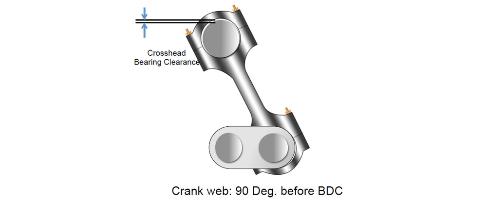
- Turn the crankshaft so that the web is 90 deg. before BDC towards the exhaust side
- Measure the clearance in crosshead bearings through the inspection hole of the thrust piece by inserting a feeler gauge at top of upper bearing shell
- When checking the clearance, the discrepancy between the actual and measured values is noted and if it exceeds 0.1 mm, crosshead bearing must be inspected.
Crosshead bearing of MAN engine should be replaced when the groove width ‘X’, channeled in the surface is reduced by half.
Crank Pin Bearing
The crank pin bearings are attached at the bottom end part of the connecting rod on the crankshaft crank. It helps the connecting rod to transfer the reciprocating motion to rotary motion in a smooth manner.
Oil to lubricate the crankpin bearing is supplied through a hole drilled in the conrod from the crosshead.

Material:
Both the shells of crank pin bearing are made up of tin based white metal.
Clearance:
The bottom clearance between the journal and the new bearing shell is a result of a summation of the production tolerances of the bearing assemblies.
Following points to be considered while taking the clearance of crankpin bearing.
- Open the crankcase doors of main engine
- Ensure crankcase is properly ventilated before entry
- Turn the concerned crank to BDC
- Measure the clearance in the crankpin bearing by inserting a feeler gauge at the bottom of the bearing shell on both sides
- When checking the clearance, the discrepancy between the actual and measured value is noted and if it exceeds 0.1 mm, crosshead bearing must be inspected
- The wear limit for the crankpin bearing shells is based on an evaluation of the bearing condition at the time of inspection. An average wear rate of 0.01 mm per 10,000 hours is regarded as normal
In modern shell bearings, the clearance is manufactured into the shells. When the clearance has reached a maximum value as laid down in the instruction manual, the bearing has to be changed.
Thick wall shell bearings fitted in some engines have the clearance adjusted by fitting shims between the bearing halves. The shims are of equal thickness on both sides of the bearing housing.
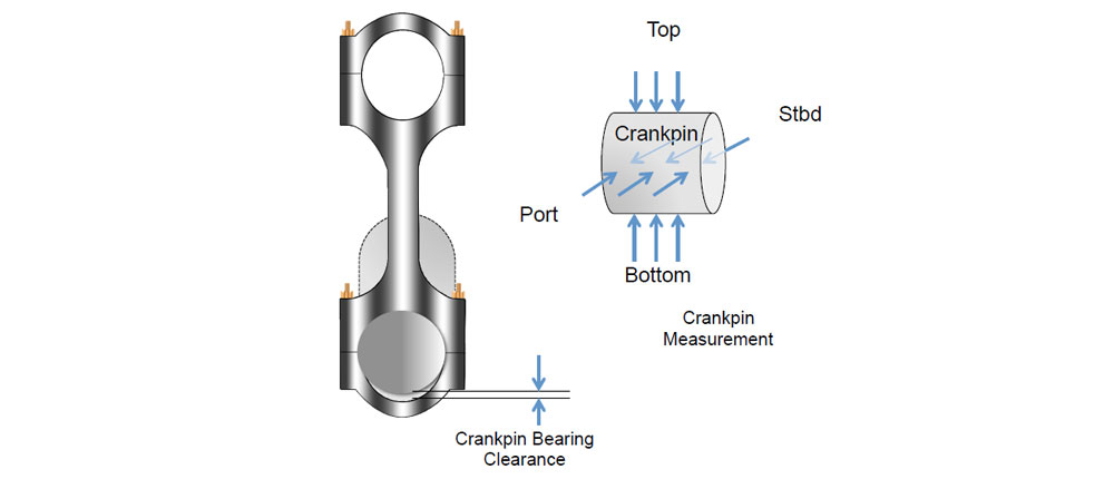
Crank pin measurement:
Heavy loading of engine may lead to wear down of main bearing or deformation of crank pin of the crankshaft. The crank pin ovality may result in increase in the bearing clearance, hence lube oil may not be retained and which can cause bearing wipe out.
Crank pin measurement is done by outside micrometer at three different positions along the length of the pin. The measurement is taken at Port-Starboard and Top-Bottom positions. Handle the micrometer carefully to avoid scratching the pin while taking measurement.
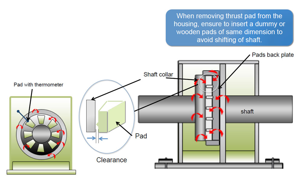
Thrust Bearing
When the crank throw is loaded by the gas pressure through the connecting rod mechanism, the arms of the crank throw deflect in the axial direction of the crankshaft, generating axial vibrations.
These vibrations may be transferred to the ship’s hull through the thrust bearing. The thrust bearing is incorporated in the aft end of the bedplate as differential expansion of the shaft and hull is minimum at the aft due to fuel heating in tanks.
The aft-most cross girder is therefore designed with ample stiffness to transmit the variable thrust from the thrust collar to the engine seating.
It is advised to align the thrust bearing when main bearing alignment is carried out to achieve accuracy.
Material
Michell type pads bearing arrangement consists of a steel forged thrust shaft, a bearing support, and segments of cast iron with white metal.
The thrust shaft is connected to the crankshaft and the intermediate shaft with fitted bolts.
The thrust shaft has a collar for transfer of the ‘thrust’ through the segments to the bedplate.
Lubrication of the thrust bearing takes place from the system oil of the engine. At the bottom of the bearing there is an oil sump with an outlet to the oil pan.
Clearance
The clearance in the thrust bearing is measured during test bed trials of the engine.
For a new engine the clearance is 0.5-1.0 mm, and for an engine in service it must not exceed 2.0 mm.
Dismount the foremost segment stopper On top of the thrust segment, a wear groove of 1mm is provided (a segment with thermometer). To measure the wear, push the thrust pad with crowbar against thrust cam to eliminate any gap at the back
While Inserting feeler gauge in the groove, if 0.1 mm is not able to enter, it indicates wear is more then 0.9 mm and the bearings need to be overhauled.
If the white metal is found scored, fine scrapping can be done to wipe off the scoring marks. The liner shims can be inserted at the back of the thrust shoes to make the clearance of all thrust pads equal. This avoids uneven loading of pads