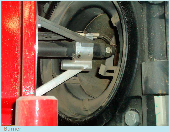
Types of Marine Boiler Burner
In a marine boiler, oil fired burner is normally used with diesel or heavy fuel oil as burning fuel. The fuel to be used has to be clean and with correct temperature and viscosity for rapid combustion.
This is to ensure that the fuel is at right atomization that will turn the fuel into micro droplets for efficient combustion.
Temperature is a critical factor during combustion, as a lower than normal temperature will lead to increase in the size of droplets, resulting in poor combustion and producing soot and smoke.
If the fuel temperature is too high, the droplets will be too small causing rapidly burning of the fuel near the burner tip. For a marine boiler, three basic types of burners are used:
- Pressure Jet Burner
- Air or Steam Blast Atomizer
- Rotary Cup Burner
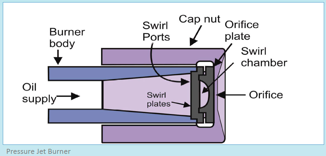
Pressure Jet Burner
The main purpose of boiler burner is to break the oil into fine droplets i.e. to atomize the fuel in correct manner so that efficient combustion can be achieved. In pressure jet burner, an orifice or nozzle is fitted at the end of a pressure tube, which atomizes the fuel in to fine droplets.
Atomization of fuel also mainly depends on the flow rate of the fuel from the burner’s end. The difference in the pressure of the fuel before and after the nozzle controls the flow-rate of the fuel from the burner. Hence, if the flow rate of the fuel from the burner is reduced to 50%, it will affect the atomization by a drop of 25%. To overcome this problem, this type of burner is supplied with different sizes of nozzles (having different diameter of orifice), which can be interchanged as per the flow rate of the fuel and the boiler steam load.
The fuel pressure required for pressure jet burner may vary from 7 bar to 15 bar depending upon the design of burner and load of the boiler. The maximum required viscosity at the burner inlet is normally 15 cst and both diesel and heavy oil can be used as fuel.
Advantages of Pressure jet burner:
- Simple in construction
- Economical in maintenance
- Variety of sizes available for different boiler loads
- Can be accommodated in all type of furnaces
- Produces variety of flame: short and fat, long and thin
Disadvantages:
- Limited turndown ratio for same nozzle size- 2:1
- Nozzle hole prone to frequent clogging
- Burner requires highest oil- pre heat treatment
- Nozzle cleaning to be carefully done as it can be damaged easily
- Requires frequent maintenance
- Inefficient at higher boiler load
2. Air or Steam Blast Atomizer
The working of this type of burner is similar to that of a pressure jet, with an addition of high pressure steam/air supply arrangement. The oil is thus sprayed in the path of the high pressure air or steam which helps the fuel for atomization. Normally air is used during the initial starting of the burner and then steam takes over the operation.
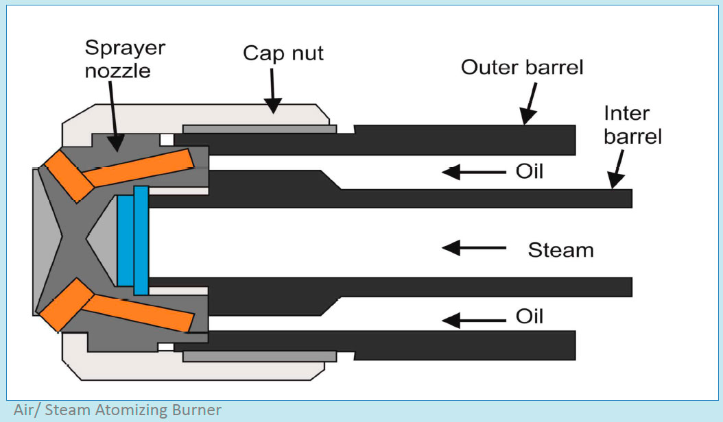
A convergent divergent nozzle is used to convert the pressure energy to kinetic energy, which results in a high velocity jet of steam and enables atomized oil is sprayed in its path. The steam side have tangential nozzle, which provides rotatory motion to the fuel for efficient combustion.
The fuel pressure required for pressure jet burner may vary from 10 bar to 21 bar depending upon the design of the burner and load of the boiler. The maximum required viscosity at the burner inlet is normally 15 cst and both diesel and heavy oils can be used as fuel.
Advantages:
- Robust construction
- High Turndown ratio of 4:1
- Efficient combustion over whole firing range
- Air fuel ratio can be adjusted for achieving higher efficiency
- Good combustion of heavy fuel oil
Disadvantages:
- Combustion depends on steam/ air supply
- Additional maintenance of connections and piping for air and steam
3. Rotary Cup Burner
As the name suggest, this burner comprises of a burner nozzle covered by a rapidly rotating cone. The fuel oil is carried on to a nozzle that is centrally located within the rotating cone. As the fuel oil moves along the cup, due to absence of centripetal force the oil film becomes thinner in its course as the circumference of the cup increases.
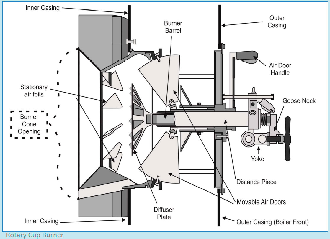
Ultimately, the fuel is discharged from the tip of the rotating cone in the form of fine atomized spray.
The atomization achieved in the rotating cup burner has a very high turndown ratio as compared to that of pressure jet burner, as atomization is achieved by the rotating cup rather than pressurizing the fuel supply to the nozzle.
Advantages:
- Good turndown ratio of 4:1
- Good atomization of heavy fuel oils
- Lowest oil pre-heat temperature required for atomization
- No high pressure fuel in the line
Disadvantages:
- Complex in construction
- Costly to maintain
- Electrical consumption and connections required for the cup drive
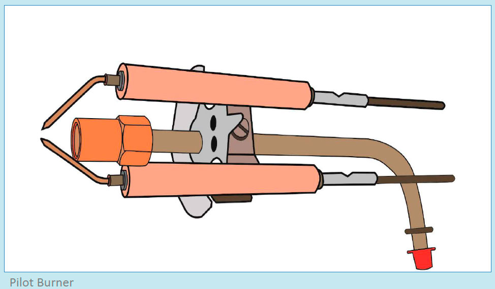
Pilot or Ignition Burner:
In some marine boilers with main burner firing in heavy fuel oil, it is very difficult to initially start the boiler with the main burner. For start up of such boiler, a separate pilot or ignition burner is provided which uses diesel oil as fuel.
This enables the pilot burner to ignite even at the coldest condition the ship faces at sea. The pilot burner has a separate diesel oil piping and pump arrangement. The heat source is provided by two electrodes, which are used for igniting the pilot flame and are fitted to a high voltage ignition transformer. The pilot burner is allotted with a limited time of ignition, during which it acts as a source of heat for the main burner and once the time is over, the pilot flame goes off.
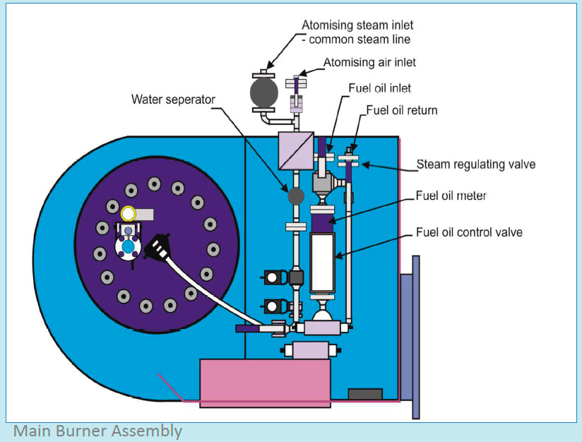
Maintenance and Inspection of Boiler Burner
The maintenance of the complete burner assembly includes inspection main burner, burner register and flame stabilizer, atomizer, pilot burner and fuel oil system.
The maintenance depends either on the maker’s instruction or on the condition of burner parts (breakdown maintenance); but a general overview of when and how the maintenance to be done for different systems and parts associated with the boiler burner is explained below:
A two weekly routine should be followed for maintenance of the following-
Fuel Oil Supply System
- Check fuel pipe work for any leakage
- Check flanges, joints and connections for leakages
- Check the manual valves are operating properly
- Check there is no leakage from any part of the valve (i.e valve gland etc.)
- Check the condition of lagging on the heavy oil pipes
- Check the tracing steam lines are working fine
- Check all the steam traps in the tracing steam lines are in working condition
- Clean and inspect the heavy oil filters provided in the line
- Ensure pneumatic/ solenoid valves installed before pilot and main burner are working correctly
- Ensure the fuel supply pump is changed to standby and all parameters are in normal operating range
- Ensure all the line filters are clean
Main Burner:
- Check the condition of nozzle for clogging
- Check there is no leakage or dripping from the burner
- Check all the connections are tightened and wiring is in good condition
- Check the solenoid valve controlling the fuel in the main burner is working fine
- Ensure there is no leakage from the solenoid valve connection
- Check and clean the cup for hard deposits in rotary cup burner
- Check the burner nozzle size is as per the load demand of the steam
- Ensure the trip limit switch on the burner door is working fine as the boiler will not fire until the door is properly shut
- Check the oil passage in the burner is cleaned with diesel oil and is free from HFO deposits
- Ensure the fan inlet is kept clean off all deposits and obstructions
- Make sure the burner register is kept clean
- Check the air passage to register for deposits and dust
- Ensure flame stabilizer is inspected and kept clean from carbon deposits
- Flame stabilizer should be checked for heat corrosion
Atomizer:
- Clean the atomizer before inspection
- Use paraffin to soak the atomizer to loosen the hard sticky carbon deposits
- Use soft metal scrapper to remove the hard deposits (never use hardened scrapper as it can damage the atomizer surface)
- Check for surface damage
- Check and clean all the holes in the atomizer
- Change the O-ring every time the atomizer is opened
- Before changing the cap nut, ensure the threads are covered with a nonhardening high temperature compound
Ignition Burner:
- Check and clean the burner nozzle
- Check the atomization of fuel in the workshop. If the atomization is poor even after cleaning the nozzle, replace it with a new one
- Clean the electrodes with electro-cleaner solution
- Check electrodes for damages
- Check the condition of ceramic insulation of the electrodes for any damage
- While performing maintenance, ensure not to change angle of the electrodes with respect to the nozzle as it may cause problems in ignition, instability and building up of carbon deposits
Forced Draft Fan
- Remove and overhaul the electric motor as per PMS
- Dismount the nuts that fix the front plate. Remove the front plate by means of a lifting device or tackle
- Dismount the end bolt and plate of the shaft, and replace the end bolt by a similar short bolt
- Mount a wheel-puller on threaded holes located on the hub plate. Tighten the wheel-puller until the impeller is loose
- Dismount the wheel-puller and end bolt once the impeller is loose. The impeller can now be pulled out from the spiral casing
- Clean the impeller carefully as dust or deposits causes imbalance or vibration
- High pressure compressed air cleaner to be used for cleaning the deposits
- If deposits are hard, scrapper tool to be used
- Check for any water in the spiral casing and same should be drained off
- Check for fuel accumulation in the casing and find out the cause for the same
- Ensure the impeller is properly cleaned and balanced while installing it on the shaft
- During starting, check for any sign of vibration
- If vibration exists, open the casing and check the cause of the same
Combustion Air: Fuel/ Air Ratio
Burner air-fuel ratio plays a critical role in achieving maximum efficiency out of fuel-fired process heating systems such as furnaces, ovens, heaters, and boilers.
If the amount of air supplied is less than required, the burner will run “rich” i.e. not all fuel will burn inside the furnace. This will result in soot deposits on the heat transfer surface, which reduces the overall efficiency.
If the amount of air is more than required, all the fuel will not be burnt, leading to reduction in the efficiency.
Most high temperature direct-fired furnaces, radiant tubes, and boilers operate with about 10% - 20% excess combustion air at high firing rate for efficient combustion and to avoid building up of soot deposits on heat transfer surfaces and inside radiant tubes.
The combustion air system supplies air to the burner according to the demands of the control system. The draft loss of the burner air register is measured by a differential pressure transmitter that converts the signal to flow signal, which is used by the control system for automatic air/oil ratio control.
A directly driven centrifugal fan supplies the combustion air. The fan is mounted on a common bed frame with the motor, inlet vanes, and servo-drive unit.
The fan impeller inside the spiral housing is mounted directly on the motor shaft. The air-flow to the burner is regulated by inlet vanes mounted on the fan suction side.
Multi blade inlet vanes are installed in the passage of air near the burner, which is normally regulated by a servo-driven unit comprising of an air cylinder and an I/P positioner. A silencer can be mounted on the fan suction side.
Points to be noted when setting the air fuel ratio:
- The temperature of the combustion products as they leave the furnace
- The percentage of excess air or oxygen in flue gases, at which, the furnace now operates
- The percentage of excess air or oxygen in flue gases, at which, the furnace can operate
- The air/fuel ratio to be readjusted in order to achieve efficient combustion with change in grade of fuel
- Since atomization by air has an effect on the excess ratio, the air fuel ratio may need to be changed for Inert gas system operation
In the era of slow steaming and strict emission restrictions for ships, meeting steam demands on board requires considering important factors such as reduction of energy use and environmental impact.
For a ship professional, understanding the basics of marine boiler such as construction and design is as vital as knowing the operation and troubleshooting.
As the boiler efficiency greatly depends on the type of boiler, design and system arrangement, it is imperative to know the factors that affect the overall boiler operation in both short and long term.
References
A Guide to Boiler Operation and Maintenance Construction and Design. Anish Wankhede [2015]