Boiler tubes- problems and maintenance
Different types of tubes
Boiler tubes can be broadly classified in two categories:
1. Types as per construction:
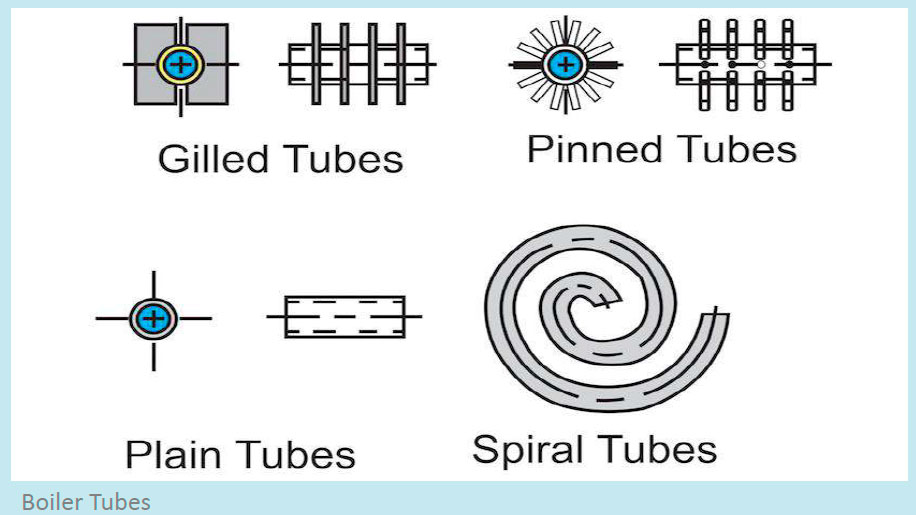
- Pin tubes
- Studded tubes
- Spiral tubes
- Seamless tubes
2. Types as per operation:
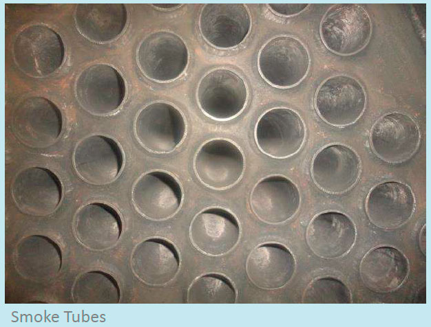
Smoke tubes
Used to carry smoke for heat transfer and are surrounded by water in a fire tube boiler.
Generating tubes
These tubes consist of a large number of small diameter tubes installed in the direction of the gas flow.
For roof-fired boilers, the generating bank may consist of one or two rows of closed-pitched tubes. In some latest modern radiant heat boilers, the generating bank has been omitted to allow the replacement of the water drum by a distribution header. The generation bank is normally heated by convection rather than radiant heat. For a set water circulation the tube diameter is limited to minimum as the ratio of steam to water can increase to a point where the possibility of overheating can occur as a result of low heat capacity of the steam. The number of tubes is limited to prevent undercooling of the gas flow, leading to dew point corrosion.
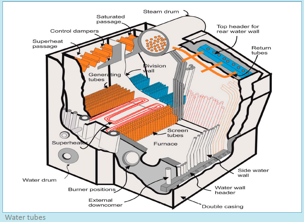
Screen tubes
These are larger bore tubes that receive the radiant heat of the flame and the convective heat of the hot gasses. The large diameter keeps the steam/water ratio down and thus prevents overheating.
The main purpose of these tubes is to protect the superheater from the direct radiant heat. On modern marine radiant heat boiler, the screen tube wall is formed out of a membrane wall.
Water-wall tubes
Contains the heat of the furnace, thus reducing the refractory and insulation requirements. Water wall tubes normally comes in three designs:
- Water-cooled with refractory covered studded tubes
- Close pitched exposed tubes
- Membrane wall tubes
Downcomers
These are large diameter unheated tubes i.e. they are fitted external to the furnace; their purpose is to feed water from the steam drum to the water drum and bottom headers.
Riser/Return tubes
These tubes return steam from the top water wall headers to the steam drum.
Superheater tubes
These are small diameter tubes in the gas flow after the screen tubes. Due to the low specific heat capacity of the saturated steam they require protection from overheating in low steam flow conditions, for e.g. when flashing.
Superheater support tubes
These are large diameter tubes designed to support part of the weight of the superheater tubes.
Tube temperature for the water-cooled sections is considered to be saturation temperature + 15°C. Solid drawn mild steel is generally used for the construction of superheater support tubes.
Tube temperature for convection superheater sections is considered to be final superheat temperature + 30oC. For radiant heat, higher temperature is considered. For Superheater tubes operating above 455oC a chrome Molybdenum alloyed steel is required.
Problems in Boiler Tube
Common problems in boiler tubes are:
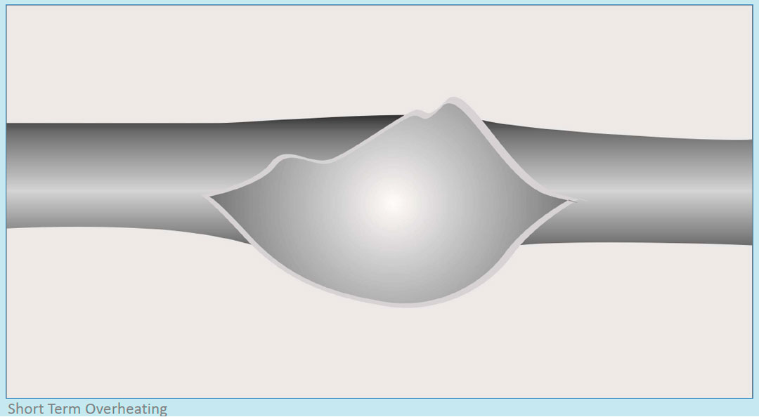
1. Short Term Overheating
Short term overheating occurs when the boiler tubes are exposed to sudden change in temperature because of following reasons-
- Low water level
- Chocking of tubes
- Major load swings
- Excessive heat input
- Wrong/rapid start-up procedure
The short term overheating can be seen as a thin lip opening along the longitudinal direction of the tube. It causes extensive tube bulging and large fish mouth appearance.
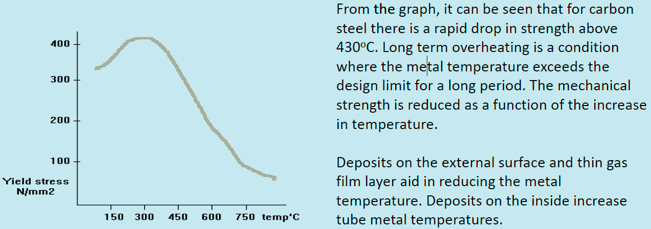
2. Long Term Overheating:
In long term overheating, the tube is exposed to a longer duration of abnormal operation. Following are the various reasons for this problem:
- Partial restriction in the steam or water flow
- Excessive heat input from burner
- Gradual accumulation of scale or deposit
- Steam blanketing in horizontal or inclined tubes
- Operation at temperature slightly above oxidation limits of given steel tube (450 °C for carbon steel)
Indications of long term overheating:
- Small to moderate bulging
- Small to moderate reduction in wall thickness
- Normally accompanied by thermal oxidation
- Found in superheaters, re-heaters, water walls
3. Damage due to Hydrogen:
Hydrogen damage of boiler tubes is normally caused by a corrosive reaction that occurs between the steam and steel: Fe + H2O = Fe3O4 + H2
In the above reaction, the hydrogen released reacts with the carbides which in-turn decarburize the steel and forms methane gas at grain boundaries.
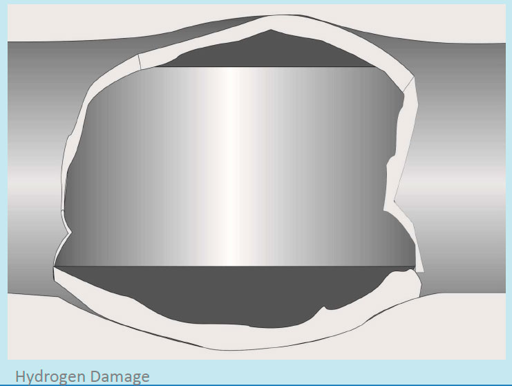
This also results in decrease in the strength of the material and leads to localized corrosion in the tubes.
This type of damage generally occurs:
- In the water-wall tubes operating above 68 bar pressure
- Beneath heavy deposits
- Where corrosion releases atomic hydrogen
If the tubes are damaged due to hydrogen, it can be identified with following signs:
- Thick-lipped damage along the longitudinal section of the tube
- Brittle appearance in the damage section
- Blown out tube creating window section
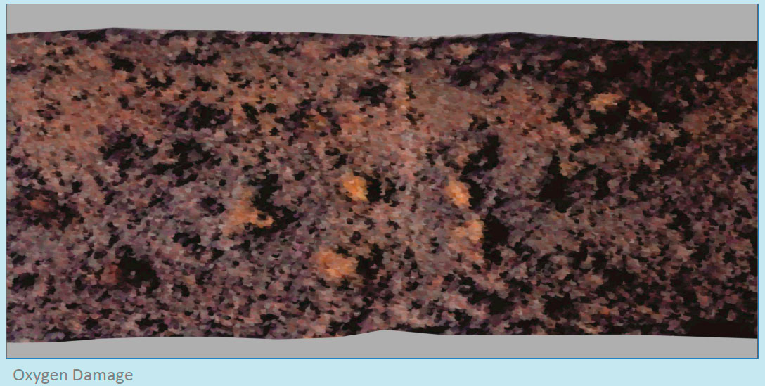
4. Damage Due to Oxygen:
Oxygen pitting occurs with the presence of excessive oxygen in boiler water. It can occur during operation as a result of in-leakage of air at pumps or failure in operation of pre-boiler water treatment equipment. This may also occur during extended out-of-service periods, such as outages and storage, if proper procedures are not followed in lay-up.
Non-drainable locations of boiler circuits such as superheater loops, sagging horizontal superheater, re-heater tubes and supply lines are mainly susceptible.
This type of damage generally occurs near:
- Economizer feed-water inlet on operating boilers
- Flooded or non-drainable surfaces
If the tubes are damaged due to oxygen, it can be identified with following signs:
- Aggressive localized corrosion and loss of tube wall
- Reddish-brown hematite (Fe2O3) or “rust” deposits or “tubercles”
- Hemispherical pitting beneath deposits
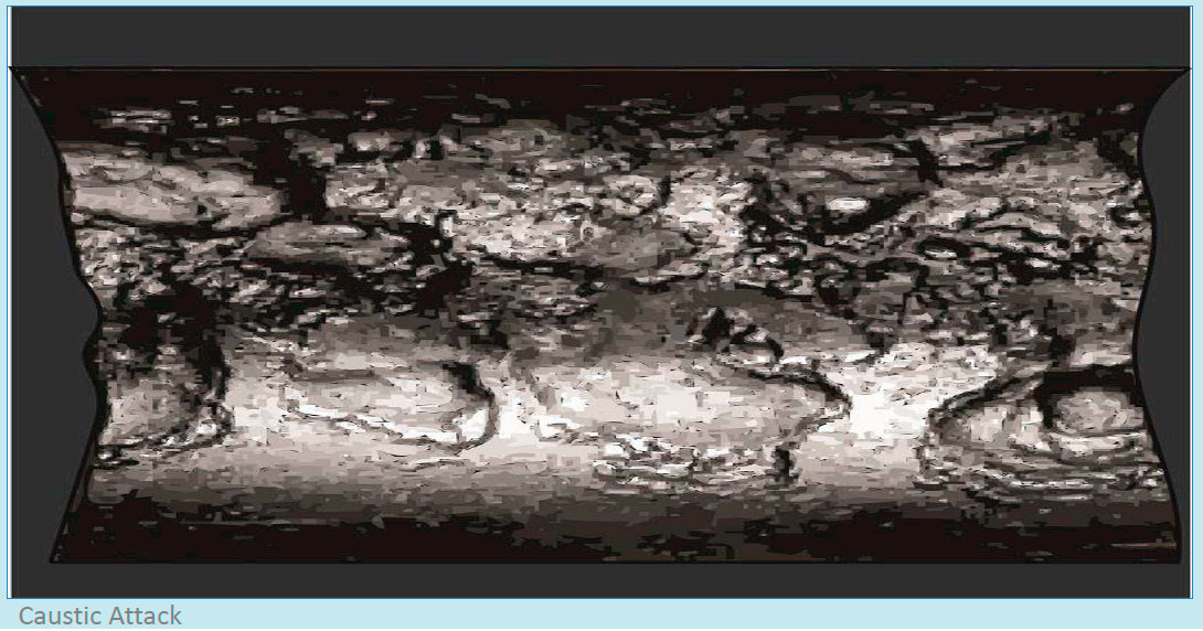
5. Damage due to Caustic Attack:
The boiler water carries impurities and deposits, which sit on the inner diameter of the tubes, causing caustic attack. This drastically increases the stress and strain in the tube walls and any abnormal operation can lead to damage in the affected tubes.
Caustic attack on tubes leads to:
- Diminishing cooling water flow in the tubes
- Boiling of Local under-deposits and concentration of boiler water chemicals
- Under influence of pH it results in corrosive attack at the inner surface, breaking the protective magnetite layer
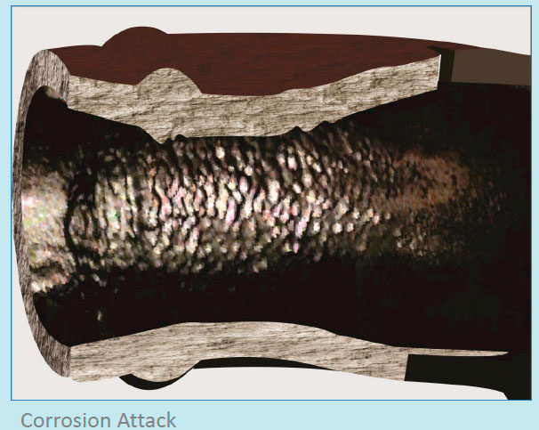
6. Corrosion Attacks:
Corrosion in the boiler tubes can be due to several reasons. Some of the types of corrosion that affects the life of boiler tubes are:
Stress corrosion: The stress corrosion is commonly seen in austenitic or stainless steel superheater materials. It leads to trans-granular and intergranular cracks that propagate in the tubes. The stress corrosion rate is much faster if both high tensile stresses and corrosive fluids are present together.
Signs of stress corrosion:
- Brittle type thick wall cracks
- Seen generally near tube attachments
- Crack propagating from internal diameter
Waterside corrosion fatigue: Tube damage occurs due to the combination of thermal fatigue and corrosion. Corrosion fatigue is influenced by boiler design, water chemistry, boiler water oxygen content and boiler operation.
A combination of these effects leads to the breakdown of the protective magnetite on the Internal surface of the boiler tubes. The loss of this protective scale exposes the tubes to corrosion. The problem is most likely to progress during boiler start-up cycles.
Signs and location of waterside corrosion fatigue:
- Buck-stay attachment, seal plate and scallop bars are most susceptible to this type of corrosion
- Wide trans-granular cracks normally adjacent to external attachments
Fireside corrosion: The outer surface of the tubes experiences high temperature fatigue stress due to soot-blowing, improper boiler operation, normal shedding of slag etc. This thermal stress with other cyclic stresses can initiate cracking of tubes with less elastic external scale, which will expose the base material to repeated corrosion.
Signs and location of fireside corrosion fatigue:
- Most commonly found on the furnace wall tubes of drum type boilers
- Series of cracks on the outer diameter of tube, propagating in the tube wall
- Elephant hide, alligator hide or craze cracking appearance (a thick russet appearance to the skin due to furrowing or cracking)
7. Acidic Corrosion:
The acid attack on the boiler tubes arises due to poor boiler chemical dosing or residual acids trapped in discontinuities post ‘passivation cleaning process’.
Signs and location of acid corrosion:
- Occurs in the Inside of the boiler tubes
- Irregular pitting marks on the internal diameter of the tubes
- Swiss cheese appearance if the acid attack is very high
Maintenance of Boiler Tubes
Boiler tubes are responsible for heat exchanging process inside the marine boiler. It is of extreme importance to carry out regular inspections and cleaning of boiler tubes to ensure that heat is transferred to the water inside the boiler in an efficient manner for generating the steam. Any interference in the heat transfer will lead to overheating of the tubes, which can even lead to a major boiler fire.
Cleaning: This process involves internal and external cleaning of tubes to remove deposits and impurities. Cleaning processes and intervals varies according to the type of the boiler (water or smoke tube).
Cleaning of Water Tubes:
In water tube boiler, since the hot gases passes over the tube surface, it is important to remove the deposits and soot from the outer surface. The internal cleaning cannot be performed frequently as all the tube openings are inside the water and steam drums. This is when chemical dosing of boiler water comes into action.
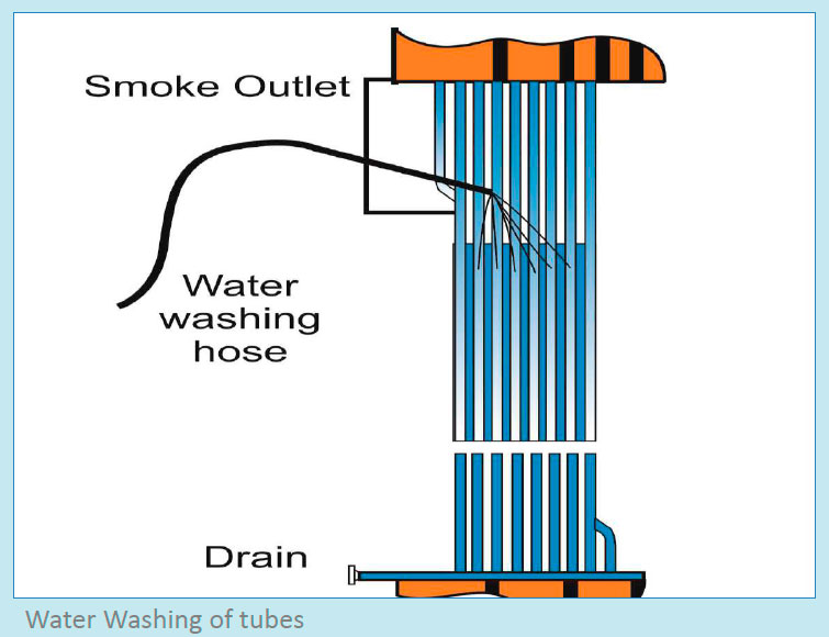
Water washing is the most commonly applied method to clean the soot deposits over the boiler water tubes . As most of the deposits consist mainly of non-soluble particles held together by a water-soluble bonding material, water washing will have the following benefits-
1. Dissolves the bonding material.
2. Washes away the loosened insoluble deposits.
The procedure for soot removal with water washing is as follows:
- Shut off the power for burner and pull out the burner assembly from the boiler furnace
- Wait approximately 10-20 minutes for the boiler furnace to cool down
- Open furnace drain valve and check that the pipe and drain are not blocked
- Unlock and remove the inspection hatches of the smoke outlet box located on top of the boiler
- Use a hand water lance. Direct a jet of fresh water at each of the vertical uptakes
- Flush carefully over each tube for 20-30 seconds with a good flow of water jet
- Water pressure should be between 4 and 6 bar
- Allow time for the washing water to drain from the furnace floor and check the drain outlet has not become blocked
Note: Care should be taken not to let water get in contact with burner throat refractory.
Cleaning of Smoke Tube Boiler:
In the smoke tube boiler, the flu gases passes through inside of the tubes, which are surrounded by water. If the tubes are covered by soot (internally) or by mud (externally) the heat transfer rate will decrease resulting in dipping of overall boiler efficiency.
For cleaning the tubes, the complete boiler needs to be shut down and the water to be drained off. Following procedure is to be performed:
- Shut off the power for boiler
- Let the boiler cool down for sufficient time
- Start draining the boiler once the pressure inside the boiler is zero
- Check the local regulations (if in port) before carrying out boiler blow down procedure
- Check and inform the dry dock personnel if in dry dock before the blow down
- Once the boiler is completely empty of water, open the top most manhole door and check the real water level
- Open other manholes on the boiler
- Remove the heat resistant lagging to access the smoke box of the boiler from both the sides
- Clean the boiler tubes internally by using a boiler tube-cleaning tool (Pneumatically supplied long rod with brush fitted at the end along with water supply arrangement. The brush rotates due to air pressure inside the tube and water spray softens the hard deposited soot)
- If the tool is not available, take a rod and a cleaning round metal brush
- Weld the brush at one end and manually clean the tubes by to and fro motion of the rod
- Fresh water to be used when cleaning the ID of tubes
- The outer surface of the tubes can be cleaned by using fresh water jet spray through the manhole doors
- Ensure the boiler drum drain valve is opened and clear
- Renew all the gaskets for smoke box cover before installation
- Renew all manhole door gaskets even if the gaskets seem in good condition
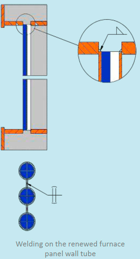
Welding:
Welding on boiler tubes is done either for temporary repairs or while re-tubing the boiler by removing the old tubes and inserting the new ones. For repairing by welding, following points to be considered:
- Welding to be performed by approved welder only
- The boiler power is to be shut down and the boiler is allowed to cool before working
- Ventilation is established for working
- Before performing re-tubing in fire tube boiler, notify the owner and class approval body for carrying out pre and post inspections
- The ends of the tubes must be firmly rolled, beaded and welded in a fire tube boiler
- Where the tubes do not exceed 1 1⁄2 inches in diameter, the tube sheet may be beveled or recessed to a depth at least equal to the thickness of the tubes and the tubes should be rolled into place and welded. In no case shall the tube end extend more than 3/8- inch beyond the tube sheet
- Tube ends not subjected to direct radiant heat of the furnace may be rolled and seal- welded without beading provided the tube ends extend in the range of 1⁄4-inch to 5/16-inch through the tube sheet; and the throat of the seal-weld is in the range of 3/16-inch to 5/16-inches
- Tubes to be re-expanded once the welding is completed
- The expanding of tubes can be done either by Prosser method or by rolling method depending on the tube’s diameter
- In the water tube boiler, tubes’ ends and neck can be fusion welded to the boiler drum without expanding or flaring only if the material used and welding comply with the SOLAS and manufacturer requirement
- In water tube boiler, forge or fusion welding may close ends of stub tubes
- For boiler and super heater tubes, seal welding can be applied into fittings or headers once they have been expanded and flared, provided the materials in the fittings or headers complies with the SOALS regulations
- Repairing of bulges in tubes in water-tube boilers is permissible when the area to be repaired does not exceed 2 inches in maximum dimension and there are no more than three such repairs in any one tube
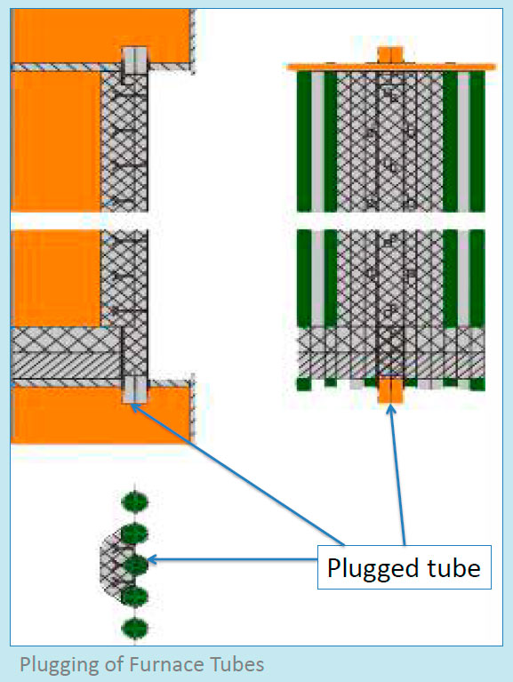
Plugging:
The boiler tube may get damaged, which can cause leakage and hamper the boiler operation. Since boiler is important machinery for engine room operation of the ship, sometimes temporary repairs are followed to stop the leakage and resume boiler operation.
One such operation is plugging of the leaky boiler tubes. In this method, first the leaking tube is determined followed by the plugging of the tube. The plugging procedure will depend on the type of the boiler.
For smoke tube boiler, following procedure to be performed while plugging any leaky tube:
- Stop and cool down the boiler
- Perform hydrostatic testing to identify which tubes are leaking
- One end on the damaged tube can be collapsed inside the tube plate after the other end has been cut clear off the tube plate. Then pull out the damaged tube
- Insert a short length tube in its place and weld it
- Insert a tapered tube plug and perform tack welding to hold the plug in place. The alternate method to hold the plug is to use a long steel bar threaded and bolted at two ends, holding the plug from its center
- Once the plugging of tubes is completed, they must be hydraulically pressure tested to confirm any leakages
- Since this is a temporary repair, a permanent repair must be planned as soon as possible
For water tube boiler, following procedure to be performed while plugging any leaky tube:
- Stop and cool down the boiler
- Open and swing out the burner door assembly and check for any sign of water leakages
- If the leakage is not visible from the burner side, open inspection door and furnace entrance door
- While checking the leakage, ensure the boiler feed pump is running
- The leakage will be indicated by pressurized water flow
- To find the leakage, operator may have to enter the generating tube section
- If no leakage is detected in the main boiler, check the exhaust gas economizer for water tube leakage
- The leaky tube can be cut and plugged
- Once the leaky tube/tubes are plugged, ensure to renew with new register or tubes as prolong operation with less tubes heightens the risk of further damage to the exposed tubes
Boiler Furnace
The furnace is the space in the boiler where the initial process of steam production takes place. Heat is generated within the furnace and transferred to boiler water to produce steam. It is important to ensure the furnace is properly maintained to avoid heat loss at the initial stage of combustion.
Types of Furnace:
A boiler furnace can be broadly cassified by the method of construction to following types :
1. Forging: The forging furnace is used for preheating billets and ingots to attain a ‘forge’ temperature. The furnace temperature is maintained at around 1200 to 1250°C. Forging furnaces use an open fireplace system and most of the heat is transmitted by radiation. The typical loading in a forging furnace is 5 to 6 tonnes with the furnace operating for 16 to 18 hours daily.
2. Rerolling mill furnace: Rerolling furnace can be further classified into:
a) Batch type: A box type furnace is employed for batch type rerolling mill. The furnace is basically used for heating up scrap, small ingots and billets weighing 2 to 20 kg. for rerolling. The charging and discharging of the ‘material’ is done manually and the final product is in the form of rods, strips etc. The operating temperature is about 1200 o C.
b) Continuous pusher type: The process flow and operating cycles of a continuous pusher type is the same as that of the batch furnace. The operating temperature is about 1250 °C. The material or stock recovers a part of the heat in flue gases as it moves down the length of the furnace. Heat absorption by the material in the furnace is slow, steady and uniform throughout the cross-section compared with batch type.
c) Continuous steel reheating furnaces The main function of a reheating furnace is to raise the temperature of a piece of steel, typically to between 900°C and 1250°C , until it is plastic enough to be pressed or rolled to the desired section, size or shape. The furnace must also meet specific requirements and objectives in terms of stock heating rates for metallurgical and productivity reasons.
All furnaces have the following components:
- Refractory chamber constructed of insulating materials to retain heat at high operating temperatures
- Hearth to support or carry the steel, which consists of refractory materials supported by a steel structure, part of which is water-cooled
- Burners that use liquid or gaseous fuels to raise and maintain the temperature in the chamber
- Exhaust passage to remove combustion exhaust gases from the chamber
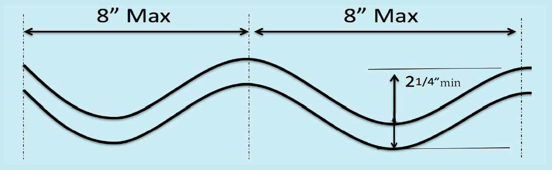
Corrugation: The plain boiler furnace geometry is corrugated to strengthen and to increase the heated surface area. Due to their shape, they can withstand elevated operating parameters of a high pressure boiler.
Mainly five types of boiler corrugations are available:
1. Leads Suspension: When corrugations are not more than 8 inches from center to center, and not less than 21/4 inches deep.
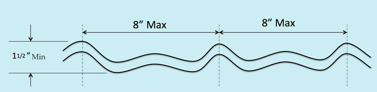
2. Deighton and morrison: In this type, the corrugations are not more than 8 inches from center to center, and not less than 11/2 inches deep.
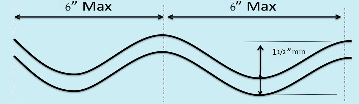
3. Fox: In this type, the corrugations are not more than 6 inches from center to center, and not less than 11/2 inches deep.
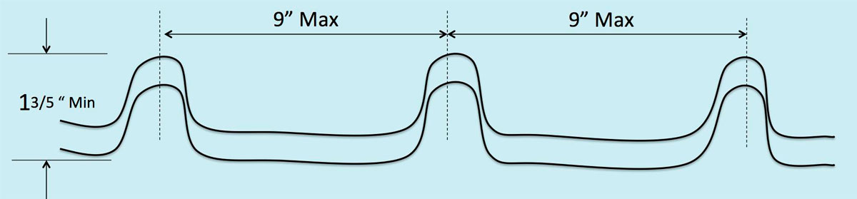
4. Purves: In this type, the corrugations are not more than 9 inches from center to center, and not less than 1 3/5 inches deep
Problems in Furnace
Boiler furnace is a primary component where the heat generation and transfer take place. A small change in the efficiency of the furnace will lead to a large change in the specific fuel consumption of the boiler. Following are a few common problems related to boiler furnace:
- Heat loss from the furnace due to poor shell insulation - The heat generated in the furnace is transferred to the boiler shell but it is contained by the outside insulation. Any damage in the insulation will lead to decrease in the furnace efficiency
- Damage in the furnace refractory
- Overheating of inner layer of refractory
- Leakage of furnace gas outside the boiler furnace
- Leakage of air in to the furnace
- Damage in the furnace door
- Crack near the welding of furnace door leading to gas leakage
- Damage to bottom blow-off pipe due to direct exposure to heat
A bottom blow-off pipe when exposed to direct furnace heat shall be protected by firebrick or other heat resisting material so arranged that the pipe could be inspected when required.
When the pressure in the furnace automatically controls the intake damper, furnace pressure is maintained slightly below the atmospheric pressure.
Maintenance of Furnace
Following points sre to be considered for carrying out furnace maintenance:
- Maintain the boiler insulation at any cost
- Maintain the refractory inside the boiler furnace
- Maintain proper sealing from manhole doors of the furnace
- Ensure to maintain the maximum surface temperature of boiler shell at about 50 °C
- If the furnace has to be rebuilt, better to use ceramic fiber blanket insulation. If refractory brick is required to withstand rough handling, an outer layer of ceramic fiber can be used
- Maintaining a slight positive furnace pressure can control air leakage in the furnace
- Cover the bottom blow off pipe by firebrick or other insulating material in such a way that the pipe may be inspected when required
Furnace Inspection:
- Check overheating distortion on furnace crown
- Check for flame impingement and dry cracks due to impingement
- Check for hairline cracks in boiler brickwork (refractory) due to changes in furnace temperature
- Check for corrosion
- Check brickwork protecting the foundation. If found damaged, it may cause distortion of bottom plating
- Check condition of water wall tubes
- Check for water leakage if visible during furnace inspection in water tube boiler
- Check for overheating of soot blowing tubes whose opening can be seen from the furnace
- Check the condition of screening tubes
- Examine the furnace end of superheater visible through screen tubes
- Check the gas baffle condition above and below the superheater
Boiler Refractory
The basic requirement of boiler refractory materials is that they should contain the heat generated in the furnace. They therefore must have good insulating properties and should be able to withstand high temperatures.
They must also have sufficient mechanical strength to resist the forces set up by the weight of the adjacent brickwork, to withstand vibration and the cutting and abrasive action of the flame and flue dust. The materials must also be able to expand and contract uniformly without cracking.
At present no single refractory material can be used economically throughout the boiler, and the choice of suitable materials for various parts of the boiler is generally governed by the temperatures to which the refractor material will be subjected.
Types of Refractory
1. Firebricks
These are formed into bricks and then fired at high temperatures in special kilns. They are made from natural clay containing alumina, silica and quartz.
2. Monolithic Refractories
The monolithic refractories are supplied in an unfired state and installed in the boiler. They are fired in situ when the boiler is put into service. This type can be further subdivided into:
- Moldable refractory: It consists of natural clay added with calcified fire clay that has been crushed and graded. This is used where direct exposure to radiant heat takes place. It must be pounded into place during installation
- Castable refractory: The castable refractory is not meant for direct exposure of flame. This refractory is thus placed behind water walls and other parts of the boiler where it is protected from direct radiant heat. The installation process is similar to that of building concrete
- Plastic chrome ore: This refractory bonded with clay, is used in the construction of studded water walls. It can resist high temperatures but has less mechanical strength, and is pounded onto steel studs welded to the tubes. These studs provide both strength and means of attachment for tile refractory
Problems in Boiler Refractory
- Spalling: Breaking away of refractory layers
- Slagging: Softening of the bricks to a liquid state due to presence of sodium or vanadium in the boiler fuel
- Shrinkage cracking: Refractories are weaker in tension than in compression or shear. Thus if compression takes place due to the expansion of the brick at high temperature, sudden cooled cracking may occur
- Failure of brick securing devices

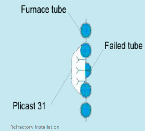
Repair and Installation of Refractory
It is the duty of ship’s engineers to check the condition of refractory at regular intervals of time. Any damage to the refractory will definitely increase the time for producing the required steam pressure, which means increase in fuel consumption of the boiler.
A quick way to examine refractory is to open the burner door and check the refractory condition. This will only take few minutes. If any part of the refractory is broken, ensure a temporary repair with available refractory at the earliest possible chance.
Before repairing the refractory material, shut off the burner and boiler. Check the properties of spare refractory mixture available onboard.
Engineers must know the mixing procedure of the paste (ratio of portion of refractory paste to water), time and setting condition.
If the refractory requires following a firing rate for setting up, it should be done accordingly. The engineers must ensure to replace temporary repairs with permanent ones (performed by qualified shore personnel) according to the manufacturer requirements.
Apart from the plastic chrome refractory, which uses tubes studs for support, other refractories must be supported by wire, external studs etc. provided as securing arrangements.
To prevent undue stresses in the refractory, ample expansion spaces must be provided. Care must be taken to ensure these spaces do not become blocked in any way as this can cause the refractory to break away from its attachments and bulge out, with the danger of possible collapse.
Ensure that when choosing and installing suitable materials for the boiler refractory, acid and alkaline substances are kept apart as at high temperatures they can react to form salts, which destroy the effectiveness of the refractory.
Superheater
A superheater is an additional small boiler, which is fitted in the water tube boiler for converting the saturated steam or wet steam in to dry steam for engine room machinery systems.
It is normally installed between water and steam drum across the superheating gas passage.
Construction: Superheaters in marine boilers are mainly of U tube or W tube construction depending upon the availability of space for superheater and steam generation capacity of the boiler.
U type superheater comprises of U tubes preferably placed vertically to the gas passage as this arrangement prevents slagging of the tube when placed in horizontal position. In this type, the tubes are supported by support plate hanging off in one of the water cooler tubes, whose diameter is increased to accommodate the support plate. Division plates are also welded on the headers. The super-heater inlet and outlet flanges are mounted on the same side.
In W tube type superheater, the tubes are placed horizontal to the flow of hot gases. The advantage of this type is that it overcomes the problem of deposits on the gas side of the superheater tubes and also avoids chocking of gas passage as there is greater length, breadth and gap between tubes.
The tubes of superheater are made of solid drawn mild steel which works at temperature of up to 455 °C . Where higher temperature operation is involved (up to 560 °C ), molybdenum steel tubes are used.
The superheater is also provided with a separate safety valve, which is set at pressure well below that of the drum safety valve setting pressure. This is done to ensure that flow of steam is maintained in the superheater under blow off condition.
Inspection:
On the gas side of the superheater, access space is provided for general cleaning and maintenance.
Check the following when inspecting superheater of a marine boiler-
- Sagging of superheater tubes between their supports
- Build-up of deposits in the superheater tubes
- Bonding slag deposits caused by vanadium bearing ash
- Support lugs situated in a high temperature zone and susceptible to thermal stress failure
- Condition of division and support plates
- Cracks In superheater due to poor steam-raising procedures, lack of expansion, or from continual carry-over of water droplets
- Condition of soot blowing arrangement for superheater
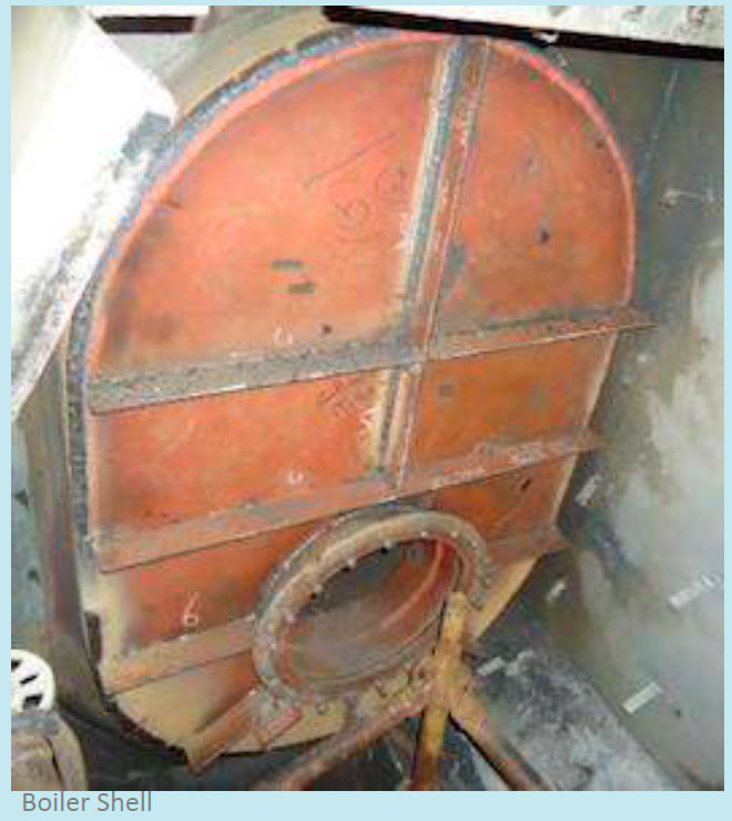
Boiler Shell
The boiler shell is pressure vessel constructed to contain the extreme pressure generated inside the boiler. The shell covers the water and combustion sides of the boiler and acts as a barrier between the atmosphere and boiler’s internal area to minimize heat loss between the two.
All the external mountings and manholes are installed over the boiler shell by cutting an opening to accommodate all the accessories. The shell strength should be properly maintained considering the number of mountings and cuttings incorporated in the boiler shell.
Construction:
Boiler shell is constructed either by riveting or welding several plates making one complete pressure vessel. For riveted construction, plates and steam space stays must have tensile strengths ranging between 430 – 560 MN/m2 provided the percentage of elongation is not less than 20 percent on a standard test length.
For welded type, the shell plate strength should be between 400 – 450 MN/m2. If the plates are to be flanged, the strength requirement will decrease but the percentage elongation must be increased to 23 % on a standard test length.
The boiler shell comprises of several mountings and manhole doors for which the shell is cut. This will weaken the strength of the shell and hence compensation is required. For any hole cut in the shell, additional material with a diameter greater than 2.5 x plate thickness + 70mm must be provided for compensating the loss of strength due to material cut out.
The largest holes cut in the shell include the manholes, and where these are cut in the cylindrical portion of the shell they must be arranged with their minor axis parallel to the longitudinal axis of the boiler.
This is because the stress acting upon the longitudinal seam is twice of that acting upon the circumferential seam.
Thus the shell must not be weakened more than necessary Boiler Shell along its longitudinal axis.
Inspection: The boiler shell must be inspected at every dry dock or during major boiler repair. Following things are to be checked while inspection:
- Ensure to wear face mask while removing the insulation lagging from shell
- Before removing the metal sheet which covers the insulation, check for black smoky marking in the sheet near the furnace side, which indicates shell leakage
- Remove the sheet and insulation lagging to access the shell
- Check for cracks and bulging in the shell
- Check carefully the area where manhole doors are welded to the shell for cracks and deformation
- Check carefully the area where valves and fittings are welded to the shell for cracks and deformation
- Ensure lagging material is sufficient to insulate the high temperature shell
- Check insulation lagging is not wet near water/ steam side of the boiler, which indicates shell leakage
Maintenance and Repair
The major maintenance done on the boiler shell is repairing welding cracks, cracks on the surface and bulge section in the shell.
References
A Guide to Boiler Operation and Maintenance Construction and Design. Anish Wankhede [2015]